ST7565S
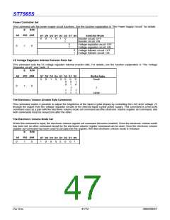
Sleep Mode
This stops all operations in the LCD display system, and as long as there are no accesses from the MPU, the consumption
current is reduced to a value near the static current. The internal modes during sleep mode are as follows:
1. The oscillator circuit and the LCD power supply circuit are halted.
2. All liquid crystal drive circuits are halted, and the segment in common drive outputs output a VDD level.
Standby Mode
The duty LCD display system operations are halted and only the static drive system for the indicator continues to operate,
providing the minimum required consumption current for the static drive. The internal modes are in the following states during
standby mode.
1 The LCD power supply circuits are halted. The oscillator circuit continues to operate.
2 The duty drive system liquid crystal drive circuits are halted and the segment and common driver outputs output a VDD level.
The static drive system does not operate.
When a reset command is performed while in standby mode, the system enters sleep mode.
* When an external power supply is used, it is recommended that the functions of the external power supply circuit be stopped
when the power saver mode is started. For example, when the various levels of liquid crystal drive voltage are provided by
external resistive voltage dividers, it is recommended that a circuit be added in order to cut the electrical current flowing through
the resistive voltage divider circuit when the power saver mode is in effect. The ST7565S series chips have a liquid crystal
display blanking control terminal /DOF. This terminal enters an “L” state when the power saver mode is launched.
Using the output of /DOF, it is possible to stop the function of an external power supply circuit.
* When the master is turned on, the oscillator circuit is operable immediately after the powering on.
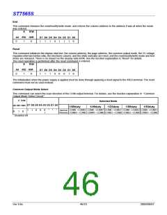
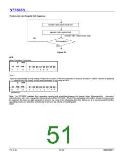
The Booster Ratio (Double Byte Command)
This command makes it possible to select step-up ratio. It is used when the power control set have turn on the internal booster
circuit. This command is a two byte command used as a pair with the booster ratio select mode set command and the booster
ratio register set command, and both commands must be issued one after the other.
Booster Ratio Select Mode Set
When this command is input, the Booster ratio register set command becomes enabled. Once the booster ratio select mode has
been set, no other command except for the booster ratio register command can be used. Once the booster ratio register set
command has been used to set data into the register, then the booster ratio select mode is released.
E
R/W
A0 /RD /WR
D7 D6 D5 D4 D3 D2 D1 D0
0
1
0
1
1
1
1
1
0
0
0
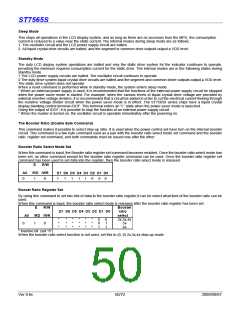
Booset Ratio Register Set
By using this command to set two bits of data to the booster ratio register,it can be select what kind of the booster ratio can be
used.
When this command is input, the booster ratio select mode is released after the booster ratio register has been set.
E
R/W
Booster
ratio
D7 D6 D5 D4 D3 D2 D1 D0
A0 /RD /WR
select
2x,3x,4x
5x
*
*
*
*
*
*
*
*
*
*
*
*
*
*
*
*
*
*
0
0
1
0
1
1
0
1
0
6x
* Inactive bit (set “0”)
When the booster ratio select function is not used, set this to (0, 0) 2x,3x,4x step-up mode
Ver 0.6c
50/72
2009/09/07

 SITRONIX [ SITRONIX TECHNOLOGY CO., LTD. ]