ST7565S
DESCRIPTION OF FUNCTIONS
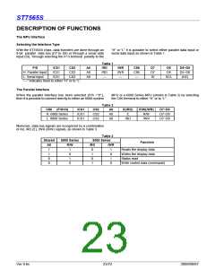
The MPU Interface
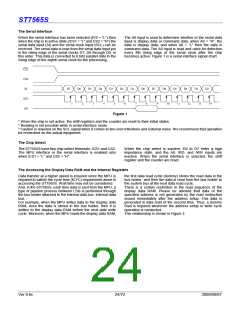
Selecting the Interface Type
With the ST7565S chips, data transfers are done through an
8-bit parallel data bus (D7 to D0) or through a serial data
input (SI). Through selecting the P/ S terminal polarity to the
“H” or “L” it is possible to select either parallel data input or
serial data input as shown in Table 1.
Table 1
P/S
/CS1
/CS1
/CS1
CS2
CS2
CS2
A0
A0
A0
/RD
/RD
—
/WR
/WR
—
C86
C86
—
D7
D7
SI
D6
D6
D5~D0
D5~D0
(HZ)
H: Parallel Input
L: Serial Input
SCL
“—” indicates fixed to either “H” or to “L”
The Parallel Interface
When the parallel interface has been selected (P/S =“H”),
then it is possible to connect directly to either an 8080-system
MPU or a 6800 Series MPU (shown in Table 2) by selecting
the C86 terminal to either “H” or to “L”.
Table 2
C86 (P/S=H)
H: 6800 Series
L: 8080 Series
/CS1
/CS1
/CS1
CS2
CS2
CS2
A0
A0
A0
E(/RD)
E
R/W(/WR)
R/W
D7~D0
D7~D0
D7~D0
/RD
/WR
Moreover, data bus signals are recognized by a combination
of A0, /RD (E), /WR (R/W) signals, as shown in Table 3.
Table 3
Shared
6800 Series
8080 Series
Function
A0
1
R/W
/RD
/WR
1
0
1
0
0
1
0
1
1
0
1
0
Reads the display data
Writes the display data
Status read
1
0
0
Write control data (command)
Ver 0.6c
23/72
2009/09/07

 SITRONIX [ SITRONIX TECHNOLOGY CO., LTD. ]