SiI 1160 PanelLink Transmitter
Data Sheet
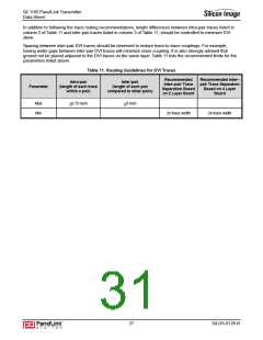
In addition to following the trace routing recommendations, length differences between intra-pair traces listed in
column 2 of Table 11 and inter-pair traces listed in column 3 of Table 11, should be controlled to minimize DVI
skew.
Spacing between inter-pair DVI traces should be observed to reduce trace-to-trace couplings. For example,
having wider gaps between inter-pair DVI traces will minimize noise coupling. It is also strongly advised that
ground not be placed adjacent to the DVI traces on the same layer. Table 11 lists the recommended limits for the
parameters listed above.
Table 11. Routing Guidelines for DVI Traces
Recommended
Inter–pair Trace
Separation Based
on 2 Layer Board
Recommended Inter–
pair Trace Separation
Based on 4 Layer
Board
Intra-pair
(length of each trace
within a pair)
Inter-pair
(length of each pair
compared to other pairs)
Parameter
Max
Min
+0.75 inch
+3 inch
2x trace width
2x trace width
27
SiI-DS-0126-B

 SILICONIMAGE [ Silicon image ]