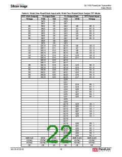
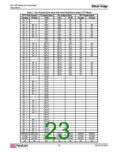
SiI 1160 PanelLink Transmitter
Data Sheet
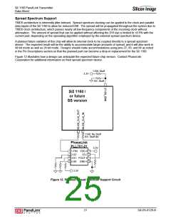
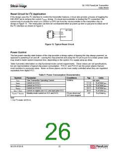
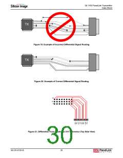
Reset Circuit for I2C Application
If the design uses the I2C interface to control the transmitter features, it must also provide a means of toggling the
ISEL/RST pin to achieve the correct TRESET timing. If a local microcontroller is hosting the I2C connection, the
easiest way to provide the reset is to connect a GPIO pin from the microcontroller to the transmitter chip as
shown in Figure 13. The reset pulse can then be commanded either at power-up time or just prior to initial use of
the I2C interface as shown in Figure 8.
SiI 1160
uC
SCL
SDA
ISEL/RST
Figure 13. Typical Reset Circuit
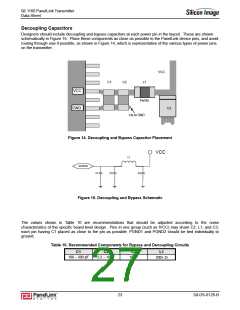
Power Control
The low-power standby state feature of the chip provides a design option of leaving the chip always powered, as
opposed to powering it on and off. Leaving the chip powered and using the PD pin to put it in a lower power state
may result in faster system response time, depending on the system Vcc supply ramp-up delay.
Table 9 provides information on chip functional mode current requirements. These values are not specifications,
but are representative of typical chip power consumption. PVCC1 and PVCC2 are the power planes that are
most sensitive to excessive noise. Noise on these planes can be more easily controlled when they are regulated
separately from digital VCC.
Table 9. Power Consumption Characteristics
Symbol
ICCT
Parameter
Total Transmitter Operating Current
Conditions
165MHz
Typ
Units
see spec.
IAVCC
Current on AVCC
17-19
31-33
10-11
38-41
>97
% of total ICCT
% of total ICCT
% of total ICCT
% of total ICCT
% of total IPD
IPVCC1
Current on PVCC1
IPVCC2
Current on PVCC2
IVCC + IIVCC
IVCCPD + IIVCCPD
Current on digital core VCC and input plan IVCC
Standby mode current on VCC and IVCC
PD pin driven low1
DVI clock stopped
Note
1. For I2C mode: bit PD=0.
SiI-DS-0126-B
22

 SILICONIMAGE [ Silicon image ]