SiI 1160 PanelLink Transmitter
Data Sheet
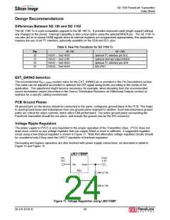
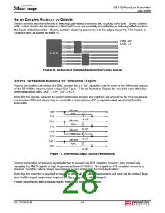
Series Damping Resistors on Outputs
Series resistors are often effective in lowering data-related emissions and reducing reflections. Series resistors
with a value close to the impedance of the board traces are generally most effective in reducing reflections from
the inputs of the transmitter. If used, resistors should be placed close to the output pins of the VGA Source or
Graphics chip, as shown in Figure 16.
DIE[0..23]/
DIO[0..23]
VGA
Figure 16. Series Input Damping Resistors for Driving Source
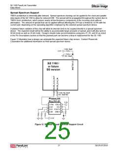
Source Termination Resistors on Differential Outputs
Source termination, consisting of a 300Ω resistor and a 0.1µF capacitor, may be used on the differential outputs
of the SiI 1160 to improve signal swings. See Figure 17 for an illustration. Repeat the circuit for each of the four
differential output pairs: TX0+, TX1+, TX2+, TXC+.
Note that the specific value for the source termination resistor and capacitor will depend on the PCB layout and
construction. Different values may be needed to create optimum DVI-compliant output waveforms from the
transmitter.
300 ohm
TX0+
TX0-
0.1uF
300 ohm
TX1+
TX2-
0.1uF
300 ohm
TX3+
TX3-
0.1uF
300 ohm
TXC+
TXC-
0.1uF
Figure 17. Differential Output Source Terminations
Source termination suppresses signal reflection to prevent non-DVI compliant receivers from erroneously
sampling the TMDS signals at high frequencies (beyond 135MHz). The impact on DVI compliant receivers is
minimal. Therefore Silicon Image recommends source termination for most applications.
Note that the capacitor is required to meet DVI idle mode DC offset requirements and must not be omitted. Note
also that the signal suppression requires the REXT_SWING value to be changed.
Power consumption will be slightly higher when using source termination.
SiI-DS-0126-B
24

 SILICONIMAGE [ Silicon image ]