SC9821C
3. REGISTER FUNCTION
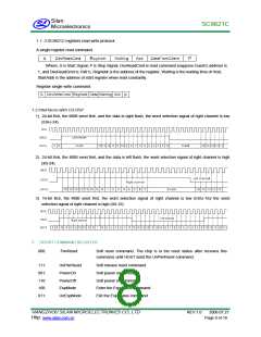
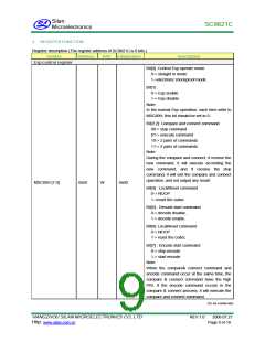
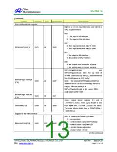
Register description (The register address of SC9821C is 8 bits.)
Symbol
Address
R/W
Initialization
Description
Esp control register
Bit[0] :Control Esp operate mode
0•> straight in mode
1•>electronic shockproof mode
Bit[1] :
0•> Esp enable
1•> Esp disable
Note:
In the normal Esp operation, each time write to
MSC80H, this bit should be set to 0.
Bit[3:2]: Compare and connect command
00•> stop command
01•> execute command
10•> 2 pairs of commands
11•> 3 pairs of commands
Note:
During the compare and connect, if receive the
new command, it will execute according the
new
command;
and
if
receive
the
stop
command, it will exit the compare and connect
operation, and not output any result.
MSC80H [7:0]
0x50
W
0x00
Bit[4] : LocalReset command
0•> NOOP
1•>reset the codec
Bit[5] : Decode start command
0•> decode disable,
1•> decode enable.
Bit[6]: LocalReset command
0•> NOOP
1•> reset the codec
Bit[7] : Encode start command
0•> stop encode
1•> start encode
Note:
When the compare& connect command and
encode command occur at the same time, the
compare & connect command have the high
PRI. If the encode command occurs in the
compare & connect process, it will execute the
compare and connect command.
(To be continued)
HANGZHOU SILAN MICROELECTRONICS CO.,LTD
Http:
REV:1.0
2006.07.21
www.silan.com.cn
Page 9 of 18

 SILAN [ SILAN MICROELECTRONICS JOINT-STOCK ]