SC9821C
(Continued)
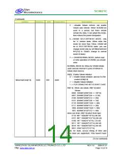
Symbol
Address
R/W
Initialization
Description
Bit[3] : Mute control signal
0•> NOOP
1•> mute operation
Bit[6:5] : Set compare & connect modes
00•> 16•bit precision
MSC83H [7:0]
0x51
W
0x00
01•> 12•bit precision
others•> 8•bit precision
Bit[7] : WAQV signal, is the data valid signal
send by MCU.
0•> NOOP
1•> data enable, execute the Valid operation
Bit[3:0] : Encoder operate modes
1000•> non•compress mode, the audio data
not compressed, and enter DRAM
buffer
0100•> 6•bit compress mode
0010•> 5•bit compress mode
0001•> 4•bit compress mode
others•> 6•bit compress mode, this is the
default mode.
Bit[5:4]: CD shock signal detect modes
00•> YFCKP falling edge, YFLAG˙0, judge
it is shock
MSC85H [7:0]
0x52
W
0x00
01•> YFCKP rising edge, YFLAG˙0, judge
it is shock
10•> YFLAG˙0, judge it is shock
11•> YFLAG = 1, judge it is shock
Bit[6]: SBSY sync modes
0•> SBSY falling edge sync, execute the
Latch operation
1•> SBSY rising edge sync, execute the
Latch operation
Note: The default mode is 0.
Esp status register
Bit[1]:
Decoder
reason.
0•> decoder normal operation, (Encoder
local reset, register execute
read/write operation, external reset).
decoder stop because the
reason, (detect the remain valid data is 0).
(To be continued)
stop
because the
internal
the
internal
MSC90H [7:0]
0x53
W
0x00
1•>
HANGZHOU SILAN MICROELECTRONICS CO.,LTD
Http:
REV:1.0
2006.07.21
www.silan.com.cn
Page 10 of 18

 SILAN [ SILAN MICROELECTRONICS JOINT-STOCK ]