SC9821C
Start Signal:
Start of frame
We define the first checking low level of DataAvail at the rising edge of SsiSClk at Guest
port as the start of frame. When check the start signal, the guest can receive the data at
the next rising edge.
Data Signal:
Ack:
Data signal
Data signal bit width sent by host computer is one SsiSClk clock cycle.
Feedback signal
1. When Guest port receives the right addressing data, it feeds back to Host signal. And
the width is an SsiSClk cycle. Used for data lead avoiding unmatched signal between two
rising edges or corresponding to the data feedback to Host.
2. When Host sends to all Guest ports, signal before sending data is as lead signal, and
between two falling edges of SsiSClk.
EndSignal:
End of frame
When Guest detects the DataAvail at rising edge of SsiSClk, it means the transmission is
end and waits for the next one.
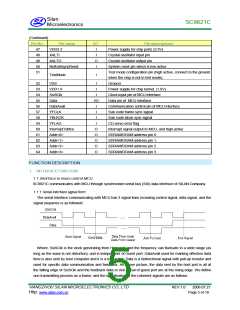
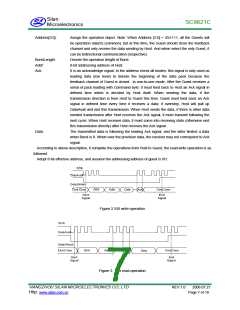
1.1. 2 Serial communication protocol processing
Host and Guest realize the communication between each other by different explanation and processing for
the data. The transmission process of one frame is as followed:
Figure 1 SSI frame signal format
In the above figure, Command pack explains the type of the frame; Addr is 8•bit address length. Data is the
transmitting data; the leading Ack is may be given to Guest by Host(Customers address check all mode
common), and may be fed back by Guest. That is all decided by the information of Command pack.
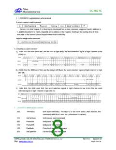
Command: In the process of the whole protocol processing, the Command pack byte is critical.
8 bits of Command byte are as followed:
Bit7
Bit6
Bit5
Bit4
Bit3
Bit2
Bit1
Bit0
Read/Write
Burst
Reset
AddrExtend
Address[3]
Address[2]Address[1]
Address[0]
Read/Write:
Read•write flag bit; 1 denotes read data from Guest to Host, and 0 denotes the data
flow is from Host to Guest.
Burst:
Cooperate with Reset
Reset:
When Burst is 0, reset is 1, denotes appointed Guest reset, at this time, have no next
byte; When Burst and Reset are 1 at the same time, denotes short command form.
The form of short command is introduced in “short command register”.
1 denotes this operation based on 16•bit address mode, and high 8•bit follows the low
8•bit; 0 is default 8•bit address operation mode.
AddrExtend:
HANGZHOU SILAN MICROELECTRONICS CO.,LTD
Http:
REV:1.0
2006.07.21
www.silan.com.cn
Page 6 of 18

 SILAN [ SILAN MICROELECTRONICS JOINT-STOCK ]