EFR32MG13 Mighty Gecko Multi-Protocol Wireless SoC Family Data Sheet
Electrical Specifications
4.1.25 USART SPI
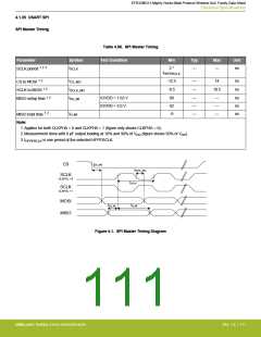
SPI Master Timing
Table 4.58. SPI Master Timing
Parameter
Symbol
Test Condition
Min
Typ
Max
Unit
SCLK period 1 2 3
tSCLK
2 *
tHFPERCLK
—
—
ns
CS to MOSI 1 2
tCS_MO
tSCLK_MO
tSU_MI
-12.5
-8.5
—
—
14
ns
ns
SCLK to MOSI 1 2
MISO setup time 1 2
10.5
IOVDD = 1.62 V
IOVDD = 3.0 V
90
42
-9
—
—
—
—
—
—
ns
ns
ns
MISO hold time 1 2
tH_MI
Note:
1. Applies for both CLKPHA = 0 and CLKPHA = 1 (figure only shows CLKPHA = 0).
2. Measurement done with 8 pF output loading at 10% and 90% of VDD (figure shows 50% of VDD).
3. tHFPERCLK is one period of the selected HFPERCLK.
tCS_MO
CS
tSCKL_MO
SCLK
CLKPOL = 0
tSCLK
SCLK
CLKPOL = 1
MOSI
MISO
tSU_MI
tH_MI
Figure 4.1. SPI Master Timing Diagram
silabs.com | Building a more connected world.
Rev. 1.4 | 111

 SILICON [ SILICON ]