C8051F52x-53x
instruction. In this case, the response time is 19 system clock cycles: 1 clock cycle to detect the interrupt,
5 clock cycles to execute the RETI, 8 clock cycles to complete the DIV instruction and 5 clock cycles to exe-
cute the LCALL to the ISR. If the CPU is executing an ISR for an interrupt with equal or higher priority, the
new interrupt will not be serviced until the current ISR completes, including the RETI and following instruc-
tion.
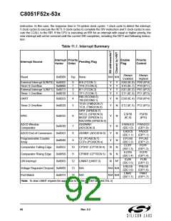
Table 11.1. Interrupt Summary
Interrupt Priority
Enable
Flag
Priority
Control
Interrupt Source
Pending Flag
Vector
Order
Always
Enabled
Always
Highest
Reset
0x0000
Top None
N/A N/A
External Interrupt 0(/INT0) 0x0003
Timer 0 Overflow 0x000B
External Interrupt 1(/INT1) 0x0013
0
1
2
3
IE0 (TCON.1)
TF0 (TCON.5)
IE1 (TCON.3)
TF1 (TCON.7)
Y
Y
Y
Y
Y
Y
Y
Y
EX0 (IE.0) PX0 (IP.0)
ET0 (IE.1) PT0 (IP.1)
EX1 (IE.2) PX1 (IP.2)
ET1 (IE.3) PT1 (IP.3)
Timer 1 Overflow
0x001B
RI0 (SCON0.0)
TI0 (SCON0.1)
TF2H (TMR2CN.7)
TF2L (TMR2CN.6)
SPIF (SPI0CN.7)
WCOL (SPI0CN.6)
MODF (SPI0CN.5)
RXOVRN (SPI0CN.4)
AD0WINT
UART
0x0023
4
5
Y
Y
N
N
ES0 (IE.4) PS0 (IP.4)
ET2 (IE.5) PT2 (IP.5)
Timer 2 Overflow
SPI0
0x002B
0x0033
ESPI0
(IE.6)
PSPI0
(IP.6)
6
Y
N
ADC0 Window
Comparator
EWADC0 PWADC0
0x003B
0x0043
0x004B
0x0053
0x005B
0x0063
7
Y
Y
Y
N
N
N
N
N
(ADC0CN.3)
(EIE1.0)
EADC0
(EIE1.1)
EPCA0
(EIE1.2)
ECPF
(EIP1.0)
PADC0
(EIP1.1)
PPCA0
(EIP1.2)
PCPF
ADC0 End of Conversion
8
AD0INT (ADC0CN.5)
Programmable Counter
Array
CF (PCA0CN.7)
CCFn (PCA0CN.n)
9
N
Comparator Falling Edge
Comparator Rising Edge
LIN Interrupt
10
11
12
13
14
CP0FIF (CPT0CN.4)
CP0RIF (CPT0CN.5)
LININT (LINST.3)
N/A
N
(EIE1.3)
(EIP1.3)
ECPR
PCPR
N
(EIE1.4)
ELIN
(EIP1.4)
PLIN
N*
(EIE1.5)
EREG0
(EIE1.6)
EMAT
(EIP1.5)
PREG0
(EIP1.6)
PMAT
Voltage Regulator Dropout 0x006B
Port Match 0x0073
N/A N/A
N/A N/A
N/A
(EIE1.7)
(EIP1.7)
*Note: To clear LININT requires the application to set the RSTINT bit (LINCTRL.3)
92
Rev. 0.3

 SILICON [ SILICON ]