C8051F52x-53x
11.4. Interrupt Register Descriptions
The SFRs used to enable the interrupt sources and set their priority level are described below. Refer to the
data sheet section associated with a particular on-chip peripheral for information regarding valid interrupt
conditions for the peripheral and the behavior of its interrupt-pending flag(s).
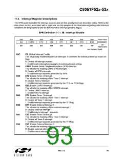
SFR Definition 11.1. IE: Interrupt Enable
R/W
R/W
R/W
R/W
R/W
R/W
R/W
R/W
Reset Value
EA
ESPI0
ET2
ES0
ET1
EX1
ET0
EX0
00000000
Bit
Bit7
Bit6
Bit5
Bit4
Bit3
Bit2
Bit1
Bit0
Addressable
SFR Address:
0xA8
Bit7:
EA: Global Interrupt Enable.
This bit globally enables/disables all interrupts. It overrides the individual interrupt mask set-
tings.
0: Disable all interrupt sources.
1: Enable each interrupt according to its individual mask setting.
ESPI0: Enable Serial Peripheral Interface (SPI0) Interrupt.
This bit sets the masking of the SPI0 interrupts.
0: Disable all SPI0 interrupts.
1: Enable interrupt requests generated by SPI0.
ET2: Enable Timer 2 Interrupt.
This bit sets the masking of the Timer 2 interrupt.
0: Disable Timer 2 interrupt.
1: Enable interrupt requests generated by the TF2L or TF2H flags.
ES0: Enable UART0 Interrupt.
This bit sets the masking of the UART0 interrupt.
0: Disable UART0 interrupt.
1: Enable UART0 interrupt.
ET1: Enable Timer 1 Interrupt.
This bit sets the masking of the Timer 1 interrupt.
0: Disable all Timer 1 interrupt.
1: Enable interrupt requests generated by the TF1 flag.
EX1: Enable External Interrupt 1.
This bit sets the masking of the external interrupt 1.
0: Disable external interrupt 1.
1: Enable extern interrupt 1 requests.
ET0: Enable Timer 0 Interrupt.
This bit sets the masking of the Timer 0 interrupt.
0: Disable all Timer 0 interrupt.
1: Enable interrupt requests generated by the TF0 flag.
EX0: Enable External Interrupt 0.
Bit6:
Bit5:
Bit4:
Bit3:
Bit2:
Bit1:
Bit0:
This bit sets the masking of the external interrupt 0.
0: Disable external interrupt 0.
1: Enable extern interrupt 0 requests.
Rev. 0.3
93

 SILICON [ SILICON ]