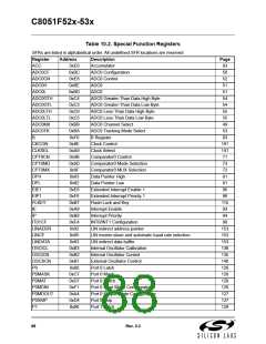
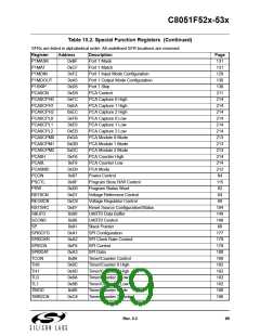
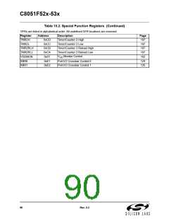
C8051F52x-53x
11. Interrupt Handler
The C8051F52x/F53x family includes an extended interrupt system with two selectable priority levels. The
allocation of interrupt sources between on-chip peripherals and external input pins varies according to the
specific version of the device. Each interrupt source has one or more associated interrupt-pending flag(s)
located in an SFR. When a peripheral or external source meets a valid interrupt condition, the associated
interrupt-pending flag is set to logic 1.
If interrupts are enabled for the source, an interrupt request is generated when the interrupt-pending flag is
set. As soon as execution of the current instruction is complete, the CPU generates an LCALL to a prede-
termined address to begin execution of an interrupt service routine (ISR). Each ISR must end with an RETI
instruction, which returns program execution to the next instruction that would have been executed if the
interrupt request had not occurred. If interrupts are not enabled, the interrupt-pending flag is ignored by the
hardware and program execution continues as normal. (The interrupt-pending flag is set to logic 1 regard-
less of the interrupt's enable/disable state.)
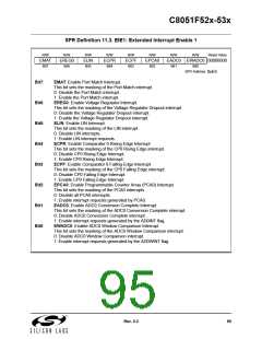
Each interrupt source can be individually enabled or disabled through the use of an associated interrupt
enable bit in the Interrupt Enable and Extended Interrupt Enable SFRs. However, interrupts must first be
globally enabled by setting the EA bit (IE.7) to logic 1 before the individual interrupt enables are recog-
nized. Setting the EA bit to logic 0 disables all interrupt sources regardless of the individual interrupt-
enable settings. Note that interrupts which occur when the EA bit is set to logic 0 will be held in a pending
state, and will not be serviced until the EA bit is set back to logic 1.
Some interrupt-pending flags are automatically cleared by the hardware when the CPU vectors to the ISR.
However, most are not cleared by the hardware and must be cleared by software before returning from the
ISR. If an interrupt-pending flag remains set after the CPU completes the return-from-interrupt (RETI)
instruction, a new interrupt request will be generated immediately and the CPU will re-enter the ISR after
the completion of the next instruction.
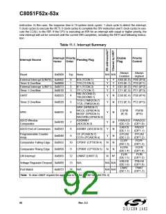
11.1. MCU Interrupt Sources and Vectors
The MCUs support 15 interrupt sources. Software can simulate an interrupt by setting any interrupt-pend-
ing flag to logic 1. If interrupts are enabled for the flag, an interrupt request will be generated and the CPU
will vector to the ISR address associated with the interrupt-pending flag. MCU interrupt sources, associ-
ated vector addresses, priority order, and control bits are summarized in Table 11.1 on page 92. Refer to
the data sheet section associated with a particular on-chip peripheral for information regarding valid inter-
rupt conditions for the peripheral and the behavior of its interrupt-pending flag(s).
11.2. Interrupt Priorities
Each interrupt source can be individually programmed to one of two priority levels: low or high. A low prior-
ity interrupt service routine can be preempted by a high priority interrupt. A high priority interrupt cannot be
preempted. Each interrupt has an associated interrupt priority bit in an SFR (IP or EIP1) used to configure
its priority level. Low priority is the default. If two interrupts are recognized simultaneously, the interrupt with
the higher priority is serviced first. If both interrupts have the same priority level, a fixed priority order is
used to arbitrate, given in Table 11.1.
11.3. Interrupt Latency
Interrupt response time depends on the state of the CPU when the interrupt occurs. Pending interrupts are
sampled and priority decoded each system clock cycle. Therefore, the fastest possible response time is 7
system clock cycles: 1 clock cycle to detect the interrupt, 1 clock cycle to execute a single instruction, and
5 clock cycles to complete the LCALL to the ISR. If an interrupt is pending when a RETI is executed, a sin-
gle instruction is executed before an LCALL is made to service the pending interrupt. Therefore, the maxi-
mum response time for an interrupt (when no other interrupt is currently being serviced or the new interrupt
is of greater priority) occurs when the CPU is performing an RETI instruction followed by a DIV as the next
Rev. 0.3
91

 SILICON [ SILICON ]