C8051F52x-53x
9.3.1. Idle Mode
Setting the Idle Mode Select bit (PCON.0) causes the CIP-51 to halt the CPU and enter Idle mode as soon
as the instruction that sets the bit completes execution. All internal registers and memory maintain their
original data. All analog and digital peripherals can remain active during Idle mode.
Idle mode is terminated when an enabled interrupt is asserted or a reset occurs. The assertion of an
enabled interrupt will cause the Idle Mode Selection bit (PCON.0) to be cleared and the CPU to resume
operation. The pending interrupt will be serviced and the next instruction to be executed after the return
from interrupt (RETI) will be the instruction immediately following the one that set the Idle Mode Select bit.
If Idle mode is terminated by an internal or external reset, the CIP-51 performs a normal reset sequence
and begins program execution at address 0x0000.
If enabled, the Watchdog Timer (WDT) will eventually cause an internal watchdog reset and thereby termi-
nate the Idle mode. This feature protects the system from an unintended permanent shutdown in the event
of an inadvertent write to the PCON register. If this behavior is not desired, the WDT may be disabled by
software prior to entering the Idle mode if the WDT was initially configured to allow this operation. This pro-
vides the opportunity for additional power savings, allowing the system to remain in the Idle mode indefi-
nitely, waiting for an external stimulus to wake up the system.
9.3.2. Stop Mode
Setting the Stop Mode Select bit (PCON.1) causes the CIP-51 to enter Stop mode as soon as the instruc-
tion that sets the bit completes execution. In Stop mode the internal oscillator, CPU, and all digital peripher-
als are stopped; the state of the external oscillator circuit is not affected. Each analog peripheral (including
the external oscillator circuit) may be shut down individually prior to entering Stop Mode. Stop mode can
only be terminated by an internal or external reset. On reset, the CIP-51 performs the normal reset
sequence and begins program execution at address 0x0000.
If enabled, the Missing Clock Detector will cause an internal reset and thereby terminate the Stop mode.
The Missing Clock Detector should be disabled if the CPU is to be put to in STOP mode for longer than the
MCD timeout period of 100 µs.
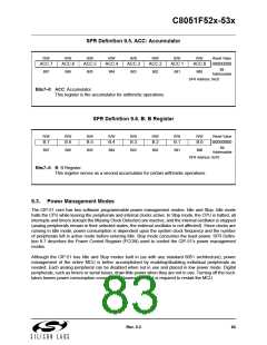
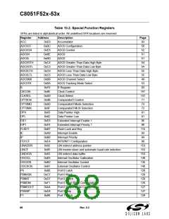
SFR Definition 9.7. PCON: Power Control
R/W
-
R/W
-
R/W
-
R/W
-
R/W
-
R/W
-
R/W
STOP
Bit1
R/W
IDLE
Bit0
Reset Value
00000000
Bit7
Bit6
Bit5
Bit4
Bit3
Bit2
SFR Address: 0x87
Bits7–2: RESERVED.
Bit1:
STOP: STOP Mode Select.
Writing a ‘1’ to this bit will place the CIP-51 into STOP mode. This bit will always read ‘0’.
1: CIP-51 forced into power-down mode. (Turns off internal oscillator).
IDLE: IDLE Mode Select.
Bit0:
Writing a ‘1’ to this bit will place the CIP-51 into IDLE mode. This bit will always read ‘0’.
1: CIP-51 forced into IDLE mode. (Shuts off clock to CPU, but clock to Timers, Interrupts,
and all peripherals remain active.)
84
Rev. 0.3

 SILICON [ SILICON ]