C8051F50x-F51x
Write to
0
PCA0CPLn
R/W when
ARSEL = 1
ENB
(Auto-Reload)
PCA0CPH:Ln
(right-justified)
PCA0PWM
Reset
A E C
C C
L L
S S
E E
L L
1 0
R C O
S O V
E V F
L
Write to
PCA0CPHn
ENB
1
PCA0CPMn
x
R/W when
ARSEL = 0
P E C C M T P E
W C A A A O W C
M O P P T G M C
1 M P N n n n F
(Capture/Compare)
Set “N” bits:
01 = 9 bits
10 = 10 bits
11 = 11 bits
PCA0CPH:Ln
(right-justified)
6 n n n
n
n
0
0 0 x 0
x
match
SET
CEXn
Enable
N-bit Comparator
S
R
Q
Q
Crossbar
Port I/O
CLR
PCA Timebase
PCA0H:L
Overflow of Nth Bit
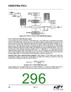
Figure 27.9. PCA 9, 10 and 11-Bit PWM Mode Diagram
27.3.6. 16-Bit Pulse Width Modulator Mode
A PCA module may also be operated in 16-Bit PWM mode. 16-bit PWM mode is independent of the other
(8/9/10/11-bit) PWM modes. In this mode, the 16-bit capture/compare module defines the number of PCA
clocks for the low time of the PWM signal. When the PCA counter matches the module contents, the out-
put on CEXn is asserted high; when the 16-bit counter overflows, CEXn is asserted low. To output a vary-
ing duty cycle, new value writes should be synchronized with PCA CCFn match interrupts. 16-Bit PWM
Mode is enabled by setting the ECOMn, PWMn, and PWM16n bits in the PCA0CPMn register. For a vary-
ing duty cycle, match interrupts should be enabled (ECCFn = 1 AND MATn = 1) to help synchronize the
capture/compare register writes. If the MATn bit is set to 1, the CCFn flag for the module will be set each
time a 16-bit comparator match (rising edge) occurs. The CF flag in PCA0CN can be used to detect the
overflow (falling edge). The duty cycle for 16-Bit PWM Mode is given by Equation 27.4.
Important Note About Capture/Compare Registers: When writing a 16-bit value to the PCA0 Cap-
ture/Compare registers, the low byte should always be written first. Writing to PCA0CPLn clears the
ECOMn bit to 0; writing to PCA0CPHn sets ECOMn to 1.
65536 – PCA0CPn
Duty Cycle = --------------------------------------------------------
65536
Equation 27.4. 16-Bit PWM Duty Cycle
Using Equation 27.4, the largest duty cycle is 100% (PCA0CPn = 0), and the smallest duty cycle is
0.0015% (PCA0CPn = 0xFFFF). A 0% duty cycle may be generated by clearing the ECOMn bit to 0.
296
Rev. 1.1

 SILICON [ SILICON ]