C8051F50x-F51x
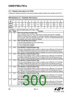
PCA0MD
C W W C C C E
I D D P P P C
D T L S S S F
L E C 2 1 0
K
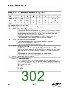
PCA0CPH5
8-bit
Comparator
Match
Reset
Enable
PCA0L Overflow
PCA0CPL5
8-bit Adder
PCA0H
Adder
Enable
Write to
PCA0CPH2
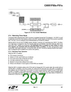
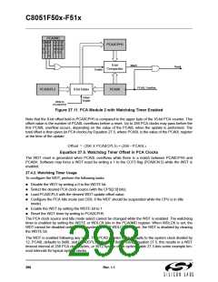
Figure 27.11. PCA Module 2 with Watchdog Timer Enabled
Note that the 8-bit offset held in PCA0CPH5 is compared to the upper byte of the 16-bit PCA counter. This
offset value is the number of PCA0L overflows before a reset. Up to 256 PCA clocks may pass before the
first PCA0L overflow occurs, depending on the value of the PCA0L when the update is performed. The
total offset is then given (in PCA clocks) by Equation 27.5, where PCA0L is the value of the PCA0L register
at the time of the update.
Offset = 256 x PCA0CPL5 + 256 – PCA0L
Equation 27.5. Watchdog Timer Offset in PCA Clocks
The WDT reset is generated when PCA0L overflows while there is a match between PCA0CPH5 and
PCA0H. Software may force a WDT reset by writing a 1 to the CCF5 flag (PCA0CN.5) while the WDT is
enabled.
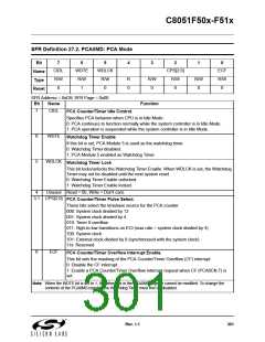
27.4.2. Watchdog Timer Usage
To configure the WDT, perform the following tasks:
Disable the WDT by writing a 0 to the WDTE bit.
Select the desired PCA clock source (with the CPS[2:0] bits).
Load PCA0CPL5 with the desired WDT update offset value.
Configure the PCA Idle mode (set CIDL if the WDT should be suspended while the CPU is in Idle
mode).
Enable the WDT by setting the WDTE bit to 1.
Reset the WDT timer by writing to PCA0CPH5.
The PCA clock source and Idle mode select cannot be changed while the WDT is enabled. The watchdog
timer is enabled by setting the WDTE or WDLCK bits in the PCA0MD register. When WDLCK is set, the
WDT cannot be disabled until the next system reset. If WDLCK is not set, the WDT is disabled by clearing
the WDTE bit.
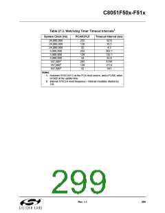
The WDT is enabled following any reset. The PCA0 counter clock defaults to the system clock divided by
12, PCA0L defaults to 0x00, and PCA0CPL5 defaults to 0x00. Using Equation 27.5, this results in a WDT
timeout interval of 256 PCA clock cycles, or 3072 system clock cycles. Table 27.3 lists some example tim-
eout intervals for typical system clocks.
298
Rev. 1.1

 SILICON [ SILICON ]