C8051F50x-F51x
Write to
0
PCA0CPLn
ENB
Reset
Write to
PCA0CPHn
ENB
1
PCA0CPMn
P E C C M T P E
W C A A A O W C
M O P P T G M C
1 M P N n n n F
PCA0CPHn
PCA0CPLn
6 n n n
n
n
1
0 0 x 0
x
match
SET
CLR
CEXn
Enable
16-bit Comparator
S
R
Q
Q
Crossbar
Port I/O
PCA Timebase
PCA0H
PCA0L
Overflow
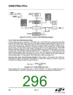
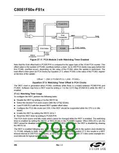
Figure 27.10. PCA 16-Bit PWM Mode
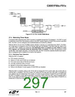
27.4. Watchdog Timer Mode
A programmable watchdog timer (WDT) function is available through the PCA Module 5. The WDT is used
to generate a reset if the time between writes to the WDT update register (PCA0CPH5) exceed a specified
limit. The WDT can be configured and enabled/disabled as needed by software.
With the WDTE bit set in the PCA0MD register, Module 5 operates as a watchdog timer (WDT). The Mod-
ule 5 high byte is compared to the PCA counter high byte; the Module 5 low byte holds the offset to be
used when WDT updates are performed. The Watchdog Timer is enabled on reset. Writes to some
PCA registers are restricted while the Watchdog Timer is enabled. The WDT will generate a reset
shortly after code begins execution. To avoid this reset, the WDT should be explicitly disabled (and option-
ally re-configured and re-enabled if it is used in the system).
27.4.1. Watchdog Timer Operation
While the WDT is enabled:
PCA counter is forced on.
Writes to PCA0L and PCA0H are not allowed.
PCA clock source bits (CPS[2:0]) are frozen.
PCA Idle control bit (CIDL) is frozen.
Module 5 is forced into software timer mode.
Writes to the Module 5 mode register (PCA0CPM5) are disabled.
While the WDT is enabled, writes to the CR bit will not change the PCA counter state; the counter will run
until the WDT is disabled. The PCA counter run control bit (CR) will read zero if the WDT is enabled but
user software has not enabled the PCA counter. If a match occurs between PCA0CPH5 and PCA0H while
the WDT is enabled, a reset will be generated. To prevent a WDT reset, the WDT may be updated with a
write of any value to PCA0CPH5. Upon a PCA0CPH5 write, PCA0H plus the offset held in PCA0CPL5 is
loaded into PCA0CPH5 (See Figure 27.11).
Rev. 1.1
297

 SILICON [ SILICON ]