C8051F39x/37x
9.2.2. Tracking Modes
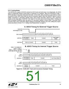
The AD0TM bit in register ADC0CN controls the ADC0 track-and-hold mode. In its default state, the ADC0
input is continuously tracked, except when a conversion is in progress. When the AD0TM bit is logic 1,
ADC0 operates in low-power track-and-hold mode. In this mode, each conversion is preceded by a track-
ing period of three SAR clocks (after the start-of-conversion signal). When the CNVSTR signal is used to
initiate conversions in low-power tracking mode, ADC0 tracks only when CNVSTR is low; conversion
begins on the rising edge of CNVSTR. See Figure 9.2 for track and convert timing details. Tracking can
also be disabled (shutdown) when the device is in low power standby or sleep modes. Low-power track-
and-hold mode is also useful when AMUX settings are frequently changed, due to the settling time require-
ments described in Section “9.2.3. Settling Time Requirements” on page 52.
A. ADC0 Timing for External Trigger Source
CNVSTR
(AD0CM[2:0]=100)
1
0
1
1
1
2
3
4
5
6
7
8
9
SAR Clocks
AD0TM=1
Low Power
or Convert
Low Power
Mode
Track
Convert
Convert
AD0TM=0
Track or Convert
Track
B. ADC0 Timing for Internal Trigger Source
Write '1' to AD0BUSY,
Timer 0, Timer 2,
Timer 1, Timer 3 Overflow
(AD0CM[2:0]=000, 001,010
011, 101)
1
0
1
1
1
2
1
3
1
4
1
1
2
3
4
4
5
5
6
6
7
7
8
9
SAR
Clocks
Low Power
or Convert
Track
Convert
Low Power Mode
AD0TM=1
1
0
1
1
2
3
8
9
SAR
Clocks
Track or
Convert
Convert
Track
AD0TM=0
Figure 9.2. 10-Bit ADC Track and Conversion Example Timing
Preliminary Rev. 0.71
51

 SILICON [ SILICON ]