SX1231
ADVANCED COMMUNICATIONS & SENSING
DATASHEET
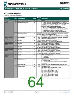
6.4. Receiver Registers
Table 24 Receiver Registers
Name
(Address)
Default
Value
Bits Variable Name
Mode
Description
7
6
-
r
0
1
unused
RegAgcRef
(0x14)
AgcAutoReferenceOn
rw
0 Æ AGC Reference is forced in AgcReferenceLevel
1 Æ AGC Reference automatically computed by the chip:
AGC Reference [dBm] = -174 + NF + DemodSnr
+10.log(2*RxBw) + AgcSnrMargin, with:
- NF = 7: LNA’s Noise Figure at maximum gain
- DemodSnr = 8 dB, SNR needed by the demodulator
- AgcSnrMargin, as set in RegAgcThresh1
- RxBw: single sideband channel filter bandwidth
5-0 AgcReferenceLevel
rw
000000 To be set as close as possible to the receiver sensitivity
(-80dBm) when AgcAutoReferenceOn = 0:
AGC Reference [dBm] = -80 - AgcReferenceLevel [dB]
7-5 AgcSnrMargin
4-0 AgcStep1
7-4 AgcStep2
3-0 AgcStep3
7-4 AgcStep4
3-0 AgcStep5
rw
rw
rw
rw
rw
rw
rw
101
SNR margin used in the receiver sensitivity calculation
RegAgcThresh1
(0x15)
(5dB) when the AgcAutoReference = 1
10000 Defines the first AGC Threshold:
(16dB) AgcThresh1 = Agc Reference + AgcStep1
0111 Defines the second AGC Threshold:
(7dB) AgcThresh2 = AgcThresh1 + AgcStep2
RegAgcThresh2
(0x16)
1011 Defines the third AGC Threshold:
(11dB) AgcThresh3 = AgcThresh2 + AgcStep3
1001 Defines the fourth AGC Threshold:
(9dB) AgcThresh4 = AgcThresh3 + AgcStep4
RegAgcThresh3
(0x17)
1011 Defines the fifth AGC Threshold:
(11dB) AgcThresh5 = AgcThresh4 + AgcStep5
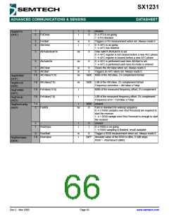
7
6
LnaZin
1
*
LNA’s input impedance
0 Æ 50 ohms
1 Æ 200 ohms
RegLna
(0x18)
LnaLowPowerOn
rw
0
LNA and mixers low-power mode:
0 Æ normal mode
1 Æ low-power mode enabled. Power consumption is
decreased
5-3 LnaCurrentGain
2-0 LnaGainSelect
r
001
000
Current LNA gain, set either manually, or by the AGC
rw
LNA gain setting:
000 Æ gain set by the internal AGC loop
001 Æ G1 = highest gain
010 Æ G2 = highest gain – 6 dB
011 Æ G3 = highest gain – 12 dB
100 Æ G4 = highest gain – 24 dB
101 Æ G5 = highest gain – 36 dB
110 Æ G6 = highest gain – 48 dB
111 Æ reserved
Rev 2 - Nov 2009
Page 64
www.semtech.com

 SEMTECH [ SEMTECH CORPORATION ]