SX1231
ADVANCED COMMUNICATIONS & SENSING
DATASHEET
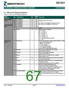
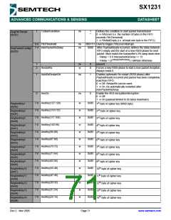
6.5. IRQ and Pin Mapping Registers
Table 25 IRQ and Pin Mapping Registers
Name
(Address)
Default
Value
Bits Variable Name
Mode
Description
7-6 Dio0Mapping
5-4 Dio1Mapping
3-2 Dio2Mapping
1-0 Dio3Mapping
7-6 Dio4Mapping
5-4 Dio5Mapping
rw
rw
rw
rw
rw
rw
r
00
RegDioMapping1
(0x25)
Mapping of pins DIO0 to DIO5
00
00
See Table 19 for mapping in Continuous mode
See Table 20 for mapping in Packet mode
00
00
RegDioMapping2
(0x26)
00
3
-
0
unused
2-0 ClkOut
rw
111
*
Selects CLKOUT frequency:
000 Æ FXOSC
001 Æ FXOSC / 2
010 Æ FXOSC / 4
011 Æ FXOSC / 8
100 Æ FXOSC / 16
101 Æ FXOSC / 32
110 Æ RC (automatically enabled)
111 Æ OFF
7
ModeReady
r
1
Set when the operation mode requested in Mode, is ready
- Sleep: Entering Sleep mode
- Standby: XO is running
RegIrqFlags1
(0x27)
- FS: PLL is locked
- Rx: RSSI sampling starts
- Tx: PA ramp-up completed
Cleared when changing operating mode.
6
5
4
3
2
RxReady
TxReady
PllLock
Rssi
r
0
0
0
0
0
Set in Rx mode, after RSSI, AGC and AFC.
Cleared when leaving Rx.
r
r
Set in Tx mode, after PA ramp-up.
Cleared when leaving Tx.
Set (in FS, Rx or Tx) when the PLL is locked.
Cleared when it is not.
rwc
r
Set in Rx when the RssiValue exceeds RssiThreshold.
Cleared when leaving Rx.
Timeout
Set when a timeout occurs (see TimeoutRxStart and
TimeoutRssiThresh)
Cleared when leaving Rx or FIFO is emptied.
1
0
AutoMode
r
0
0
Set when entering Intermediate mode.
Cleared when exiting Intermediate mode.
Please note that in Sleep mode a small delay can be
observed between AutoMode interrupt and the
corresponding enter/exit condition.
SyncAddressMatch
r/rwc
Set when Sync and Address (if enabled) are detected.
Cleared when leaving Rx or FIFO is emptied.
This bit is read only in Packet mode, rwc in Continuous
mode
Rev 2 - Nov 2009
Page 67
www.semtech.com

 SEMTECH [ SEMTECH CORPORATION ]