SX1231
ADVANCED COMMUNICATIONS & SENSING
DATASHEET
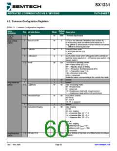
6.2. Common Configuration Registers
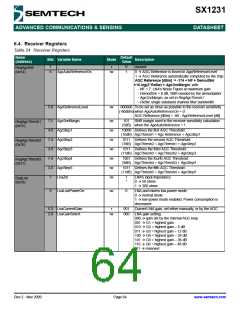
Table 22 Common Configuration Registers
Name
(Address)
Default
Value
Bits Variable Name
Mode
Description
0x00 FIFO data input/output
7-0 Fifo
rw
RegFifo
(0x00)
7
SequencerOff
rw
0
Controls the automatic Sequencer (see section 4.2 ):
0 Æ Operating mode as selected with Mode bits in
RegOpMode is automatically reached with the Sequencer
RegOpMode
(0x01)
1 Æ Mode is forced by the user
6
5
ListenOn
rw
w
0
0
Enables Listen mode:
0 Æ Off (see section 4.3)
1 Æ On
ListenAbort
Aborts Listen mode when set together with ListenOn=0
and new Mode selection in 1 SPI access (see section 4.3)
Always reads 0.
4-2 Mode
rw
001
Transceiver’s operating modes:
000 Æ Sleep mode (SLEEP)
001 Æ Standby mode (STDBY)
010 Æ Frequency Synthesizer mode (FS)
011 Æ Transmitter mode (TX)
100 Æ Receiver mode (RX)
others Æ reserved
Reads the value corresponding to the current chip mode
1-0
7
-
-
r
r
00
0
unused
unused
RegDataModul
(0x02)
6-5 DataMode
rw
00
Data processing mode:
00 Æ Packet mode
01 Æ reserved
10 Æ Continuous mode with bit synchronizer
11 Æ Continuous mode without bit synchronizer
4-3 ModulationType
rw
00
Modulation scheme:
00 Æ FSK
01 Æ OOK
10 - 11 Æ reserved
2
-
r
0
unused
1-0 ModulationShaping
rw
00
Data shaping:
in FSK:
00 Æ no shaping
01 Æ Gaussian filter, BT = 1.0
10 Æ Gaussian filter, BT = 0.5
11 Æ Gaussian filter, BT = 0.3
in OOK:
00 Æ no shaping
01 Æ filtering with fcutoff = BR
10 Æ filtering with fcutoff = 2*BR
11 Æ reserved
7-0 BitRate(15:8)
rw
0x1a MSB of Bit Rate (Chip Rate when Manchester encoding is
enabled)
RegBitrateMsb
(0x03)
Rev 2 - Nov 2009
Page 60
www.semtech.com

 SEMTECH [ SEMTECH CORPORATION ]