SX1231
ADVANCED COMMUNICATIONS & SENSING
DATASHEET
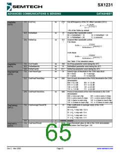
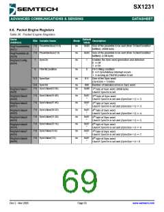
7-5 DccFreq
rw
010
*
Cut-off frequency of the DC offset canceller (DCC):
RegRxBw
(0x19)
4 × RxBw
-----------------------------------------
fc =
2π × 2DccFreq + 2
~4% of the RxBw by default
4-3 RxBwMant
2-0 RxBwExp
rw
rw
10
*
Channel filter bandwidth control:
00 Æ RxBwMant = 16
01 Æ RxBwMant = 20
10 Æ RxBwMant = 24
11 Æ reserved
101
*
Channel filter bandwidth control:
FSK Mode:
FXOSC
RxBwMant × 2RxBwExp + 2
-----------------------------------------------------------------
RxBw =
OOK Mode:
RxBw =
FXOSC
RxBwMant × 2RxBwExp + 3
-----------------------------------------------------------------
See Table 13 for tabulated values
7-5 DccFreqAfc
rw
rw
rw
rw
100
01
DccFreq parameter used during the AFC
RxBwMant parameter used during the AFC
RegAfcBw
(0x1A)
4-3 RxBwMantAfc
2-0 RxBwExpAfc
7-6 OokThreshType
011 * RxBwExp parameter used during the AFC
01
Selects type of threshold in the OOK data slicer:
RegOokPeak
(0x1B)
00 Æ fixed
01 Æ peak
10 Æ average
11 Æ reserved
5-3 OokPeakTheshStep
2-0 OokPeakThreshDec
7-6 OokAverageThreshFilt
rw
rw
rw
000
Size of each decrement of the RSSI threshold in the OOK
demodulator:
000 Æ 0.5 dB
010 Æ 1.5 dB
100 Æ 3.0 dB
110 Æ 5.0 dB
001 Æ 1.0 dB
011 Æ 2.0 dB
101 Æ 4.0 dB
111 Æ 6.0 dB
000
10
Period of decrement of the RSSI threshold in the OOK
demodulator:
000 Æ once per chip
010 Æ once every 4 chips
100 Æ twice in each chip
001 Æ once every 2 chips
011 Æ once every 8 chips
101 Æ 4 times in each chip
110 Æ 8 times in each chip 111 Æ 16 times in each chip
Filter coefficients in average mode of the OOK
demodulator:
RegOokAvg
(0x1C)
00 Æ f ≈ chip rate / 32.π
C
01 Æ f ≈ chip rate / 8.π
C
10 Æ f ≈ chip rate / 4.π
C
11 Æ f ≈ chip rate / 2.π
C
5-0
-
r
000000 unused
7-0 OokFixedThresh
rw
0110 Fixed threshold value (in dB) in the OOK demodulator.
(6dB) Used when OokThresType = 00
RegOokFix
(0x1D)
Rev 2 - Nov 2009
Page 65
www.semtech.com

 SEMTECH [ SEMTECH CORPORATION ]