LC89057W-VF4A-E
10.1.4 Switching between Master clock and clock source
•
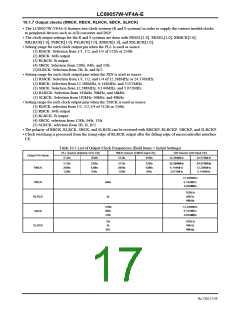
The RMCK, RBCK, and RLRCK (hereunder, R system), and the SBCK and SLRCK (hereunder, S system) clock
sources can be selected among the following three master clocks.
(1) PLL source (256fs or 512fs)
(2) XIN source (12.288MHz or 24.576MHz)
(3) TMCK source (256fs or 512fs)
•
•
•
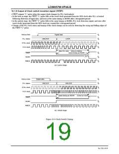
There are two ways available for clock source switching; one is to set with the R system and the S system interlocked,
and the other is to set only the R system while XIN source is fixed in the S system. This setting is carried out with
SELMTD, OCKSEL, and RCKSEL.
The clock source is automatically switched between PLL clock and XIN clock by locking/unlocking the PLL. During
this period, continuity of the clock is maintained. However, if the clock source is switched with SELMTD, continuity
of the S system is not maintained.
The clock source can be switched to XIN with OCKSEL and RCKSEL, regardless of the PLL status. The clock source
switch command and each clock output of the R and S systems are shown below.
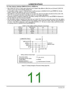
Table 10.1 Correspondence between Clock Source Switch Commands and Clock Output Pins
SELMTD
R System Output Clock
According to OCKSEL
According to RCKSEL
S System Output Clock
According to OCKSEL
Fixed to XIN source
0
1
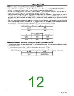
Table 10.2 Relationship between Clock Source Switch Commands and Clock Sources when PLL Locked/Unlocked
R System Clock Source
S System Clock Source
SELMTD
OCKSEL
RCKSEL
Locked
PLL
Unlocked
XIN
Locked
PLL
Unlocked
XIN
0
1
X
X
0
1
0
1
XIN
XIN
XIN
XIN
X
X
PLL
XIN
XIN
XIN
XIN
XIN
XIN
XIN
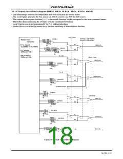
•
•
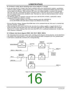
TMCK source should be selected with EXYSNC and the input clock frequency (256fs or 512fs) should be set with
PLLSEL. The same action as the one of PLL source should be taken except inputting clock from TMCK on this setting.
When data synchronized with the TMCK source is input, various clocks are output with the TMCK source as the
master clock, in a manner similar to the PLL clock status. In this case as well, the source is switched to XIN with
OCKSEL and RCKSEL. When the TMCK source is not supplied or the input data is not synchronized, the source is
switched to the XIN source, in a manner similar to the PLL source unlocked status.
•
•
The PLL status can be always monitored with RERR even after switching to the XIN source. Moreover, the processed
information can be read with the microcontroller interface regardless of the PLL status.
When the PLL changes from the locked status to the unlocked, the timing for switching the clock from the PLL source
to the XIN source can be changed with XTWT [1:0]. Use these commands if noise occurs during clock switching.
No.7202-15/59

 SANYO [ SANYO SEMICON DEVICE ]