LA76810A
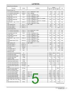
Continued from preceding page.
Ratings
typ
Parameter
Symbol
Conditions
Unit
min
max
[Chroma block]: PAL
ACC amplitude characteristics 1
ACC amplitude characteristics 2
ACCM1_P
ACCM2_P
RB_P
Input: +6dB/0dB 0dB = 40IRE
Input: -20dB/0dB
0.8
1.0
1.0
1.2
deg
deg
deg
0.7
1.1
Demodulation output ratio
R-Y/B-Y: PAL
R-Y/B-Y_GainBalance_DAC,
R-Y/B-Y_Angle_DAC = Center
0.50
0.56
0.67
Demodulation output ratio
G-Y/B-Y: PAL
Demodulation output ratio
G-Y/R-Y: PAL
Demodulation angle R-Y/B-Y:
PAL
GB_P
GR_P
R-Y/B-Y_GainBalance_DAC,
R-Y/B-Y_Angle_DAC = Center, R-Y= no-signal
R-Y/B-Y_GainBalance_DAC,
R-Y/B-Y_Angle_DAC = Center, B-Y = no-signal
R-Y/B-Y_GainBalance_DAC,
R-Y/B-Y_Angle_DAC = Center
-0.21
-0.56
85
-0.19
-0.51
90
-0.17
-0.46
95
deg
deg
deg
ANGBR_P
Killer operating point
APC pull-in range (+)
APC pull-in range (-)
[Chroma block]: NTSC
KILL_P
0dB = 40IRE
-36
-30
-23
dB
Hz
Hz
PULIN+_P
PULIN-_P
350
-350
ACC amplitude characteristics 1
ACC amplitude characteristics 2
ACCM1_N
ACCM2_N
RB_N
Input:+6dB/0dB 0dB = 40IRE
Input:-20dB/0dB
0.8
0.7
1.0
1.0
1.2
1.1
deg
deg
deg
Demodulation output ratio
R-Y/B-Y: NTSC
Demodulation output ratio
G-Y/B-Y: NTSC
Demodulation angle B-Y/R-Y:
NTSC
Demodulation angle G-Y/B-Y:
NTSC
R-Y/B-Y_GainBalance_DAC,
R-Y/B-Y_Angle_DAC = Center
R-Y/B-Y_GainBalance_DAC,
R-Y/B-Y_Angle_DAC = Center
R-Y/B-Y_GainBalance_DAC,
R-Y/B-Y_Angle_DAC = Center
R-Y/B-Y_GainBalance_DAC,
R-Y/B-Y_Angle_DAC = Center
0dB = 40IRE
0.80
0.90
1.00
GB_N
0.24
99
0.30
104
240
-32
0.38
109
250
-25
deg
deg
deg
ANGBR_N
ANGGB_N
227
Killer operating point
KILL_N
PULIN+_N
PULIN-_N
TINCEN
TINT+
-39
dB
Hz
APC pull-in range (+)
APC pull-in range (-)
Tint center
350
www.DataSheet4U.com
-350
10
Hz
-10
35
0
deg
deg
deg
Tint variable range (+)
Tint variable range (-)
[Deflection block]
TINT-
-35
Horizontal free-running frequency
Horizontal pull-in range
Horizontal output pulse width
fH
15500
±400
36.1
0
15625
15750
Hz
Hz
µs
V
fH PULL
Hduty
37.6
0.2
39.1
0.4
Horizontal output pulse
saturation voltage
V Hsat
Vertical free-running cycle 50
VFR50
VFR60
312.0
262.0
9.5
312.5
262.5
10.5
313.0
263.0
11.5
H
H
Vertical free-running cycle 60
Horizontal output pulse phase
Horizontal output pulse phase
HPHCENpal
HPHCENnt
HPHrange
µs
µs
µs
9.5
10.5
11.5
Horizontal position adjustment
range
5bit
±2.2
Horizontal position adjustment
maximum variability width
POR circuit operating voltage
HPHstep
200.0
ns
VPOR
BLKL0
3.70
7500
10800
1800
-1100
5.3
4.00
8300
11600
2600
-300
5.6
4.30
9100
12400
3400
500
V
ns
ns
ns
ns
V
Horizontal blanking left @0
Horizontal blanking left @7
Horizontal blanking right @0
Horizontal blanking right @7
Sand castle pulse crest value H
BLKL: 000
BLKL: 111
BLKR: 000
BLKR: 111
BLKL7
BLKR0
BLKR7
SANDH
SANDM1
5.9
Sand castle pulse crest value
M1
3.7
4.0
4.3
V
Sand castle pulse crest value L
SANDL
0.1
0.4
0.7
V
Continued on next page.
No.A0252-5/43

 SANYO [ SANYO SEMICON DEVICE ]