Rx5C348A/B
Notes:
1)
Oscillation adjustment does not affect the frequency of 32.768-kHz clock pulses output from the
32KOUT pin.
2)
If following 3 conditions are completed, actual clock adjustment value could be different from target
adjustment value that set by oscillator adjustment function.
1. Using oscillator adjustment function
2. Access to Rx5C348A/B at random, or synchronized with external clock that has no relation to
Rx5C348A/B, or synchronized with periodic interrupt in pulse mode.
3. Access to Rx5C348A/B more than 2 times per each second on average.
For more details, please contact to Ricoh.
ꢁ
How to evaluate the clock gain or loss
The oscillator adjustment circuit is configured to change time counts of 1 second on the basis of the settings of
the oscillation adjustment register once in 20 seconds or 60 seconds. The oscillation adjustment circuit does
not effect the frequency of 32768Hz-clock pulse output from the 32KOUT pin. Therefore, after writing the
oscillation adjustment register, we cannot measure the clock error with probing 32KOUT clock pulses. The way
to measure the clock error as follows:
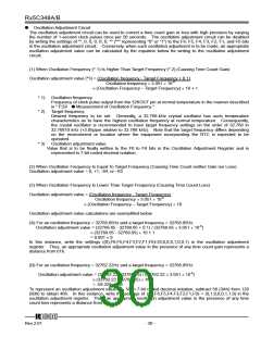
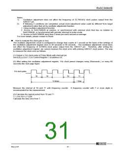
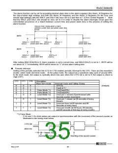
(1) Output a 1Hz clock pulse of Pulse Mode with interrupt pin
Set (0,0,x,x,0,0,1,1) to Control Register 1 at address Eh.
(2) After setting the oscillation adjustment register, 1Hz clock period changes every 20seconds ( or every 60
seconds) like next page figure.
1Hz clock pulse
T0
T0
T0
T1
19 times
1 time
Measure the interval of T0 and T1 with frequency counter. A frequency counter with 7 or more digits is
recommended for the measurement.
(3) Calculate the typical period from T0 and T1
T = (19×T0+1×T1)/20
Calculate the time error from T.
12345
Rev.2.01
- 31 -

 RICOH [ RICOH ELECTRONICS DEVICES DIVISION ]