Rx5C348A/B
ꢀ Configuration of Oscillation Circuit and Correction of Time Count Deviations
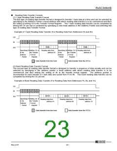
ꢁ
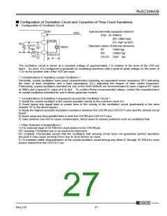
Configuration of Oscillation Circuit
Typical externally-equipped element
X’tal : 32.768kHz
VDD
VDD
(R1=30kΩ typ)
OSCIN
(CL=6pF to 8pF)
RF
CG
RD
Standard values of internal elements
32kHz
RF
RD
15MΩ typ
120kΩ typ
OSCOUT
A
CD
CG,CD 12pF typ
The oscillation circuit is driven at a constant voltage of approximately 1.2v relative to the level of the VSS pin
input. As such, it is configured to generate an oscillating waveform with a peak-to-peak voltage on the order of
1.2v on the positive side of the VSS pin input.
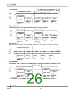
< Considerations in Handling Crystal Oscillators >
Generally, crystal oscillators have basic characteristics including an equivalent series resistance (R1) indicating
the ease of their oscillation and a load capacitance (CL) indicating the degree of their center frequency.
Particularly, crystal oscillators intended for use in the Rx5C348A/B are recommended to have a typical R1 value
of 30kΩ and a typical CL value of 6 to 8pF. To confirm these recommended values, contact the manufacturers
of crystal oscillators intended for use in these particular models.
< Considerations in Installing Components around the Oscillation Circuit >
1) Install the crystal oscillator in the closest possible vicinity to the real-time clock ICs.
2) Avoid laying any signal lines or power lines in the vicinity of the oscillation circuit (particularly in the area
marked "A" in the above figure).
3) Apply the highest possible insulation resistance between the OSCIN and OSCOUT pins and the printed circuit
board.
4) Avoid using any long parallel lines to wire the OSCIN and OSCOUT pins.
5) Take extreme care not to cause condensation, which leads to various problems such as oscillation halt.
< Other Relevant Considerations >
1) For external input of 32.768-kHz clock pulses to the OSCIN pin:
DC coupling: Prohibited due to an input level mismatch.
AC coupling: Permissible except that the oscillation halt sensing circuit does not guarantee perfect operation
because it may cause sensing errors due to such factors as noise.
2) To maintain stable characteristics of the crystal oscillator, avoid driving any other IC through 32.768-kHz clock
pulses output from the OSCOUT pin.
12345
Rev.2.01
- 27 -

 RICOH [ RICOH ELECTRONICS DEVICES DIVISION ]