Rx5C348A/B
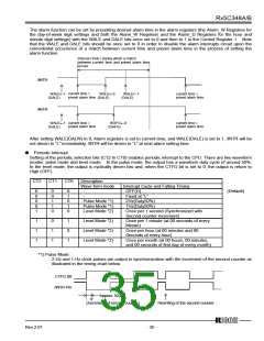
The alarm function can be set by presetting desired alarm time in the alarm registers (the Alarm_W Registers for
the day-of-week digit settings and both the Alarm_W Registers and the Alarm_D Registers for the hour and
minute digit settings) with the WALE and DALE bits once set to 0 and then to 1 in the Control Register 1. Note
that the WALE and DALE bits should be once set to 0 in order to disable the alarm interrupts circuit upon the
coincidental occurrence of a match between current time and preset alarm time in the process of setting the
alarm function.
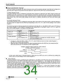
Interval (1min.) during which a match
between current time and preset alarm time
occurs
/INTR
current time =
preset alarm time
current time =
preset alarm time
WALE←1
(DALE)
WALE←1
(DALE)
WALE←0
(DALE)
/INTR
current time =
preset alarm time
current time =
preset alarm time
WALE←1
(DALE)
WAFG←0
(DAFG)
After setting WALE(DALW) to 0, Alarm registers is set to current time, and WALE(DALE) is set to 1, /INTR will be
not driven to “L” immediately, /INTR will be driven to “L” at next alarm setting time.
ꢁ
Periodic Interrupt
Setting of the periodic selection bits (CT2 to CT0) enables periodic interrupt to the CPU. There are two waveform
modes: pulse mode and level mode. In the pulse mode, the output has a waveform duty cycle of around 50%.
In the level mode, the output is cyclically driven low and, when the CTFG bit is set to 0, the output is return to
High (OFF).
CT2
CT1
CT0
Description
Wave form mode
-
Interrupt Cycle and Falling Timing
OFF(H)
0
0
0
0
1
0
0
1
1
0
0
1
0
1
0
(Default)
-
Fixed at “L”
2Hz(Duty50%)
1Hz(Duty50%)
Pulse Mode *1)
Pulse Mode *1)
Level Mode *2)
Once per 1 second (Synchronized with
Second counter increment)
Once per 1 minute (at 00 seconds of every
Minute)
Once per hour (at 00 minutes and 00
Seconds of every hour)
1
1
1
0
1
1
1
0
1
Level Mode *2)
Level Mode *2)
Level Mode *2)
Once per month (at 00 hours, 00 minutes,
and 00 seconds of first day of every month)
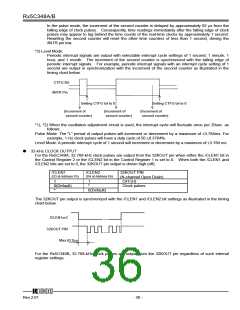
*1) Pulse Mode:
2-Hz and 1-Hz clock pulses are output in synchronization with the increment of the second counter as
illustrated in the timing chart below.
CTFG Bit
/INTR Pin
Approx. 92µs
(Increment of second counter)
Rewriting of the second counter
12345
Rev.2.01
- 35 -

 RICOH [ RICOH ELECTRONICS DEVICES DIVISION ]