Rx5C348A/B
Course (A)
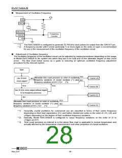
When the time count precision of each RTC is not to be adjusted, the crystal oscillator intended for use in that
RTC may have any CL value requiring no presetting. The crystal oscillator may be subject to frequency
variations which are selectable within the allowable range of time count precision. Several crystal oscillators
and RTCs should be used to find the center frequency of the crystal oscillators by the method described in "P.28
ꢁ Adjustment of Oscillation frequency" and then calculate an appropriate oscillation adjustment value by the
method described in "P.30 ꢁ Oscillation Adjustment Circuit" for writing this value to the Rx5C348A/B.
Course (B)
When the time count precision of each RTC is to be adjusted within the oscillation frequency variations of the
crystal oscillator plus the frequency variations of the real-time clock ICs, it becomes necessary to correct
deviations in the time count of each RTC by the method described in " P.30 ꢁ Oscillation Adjustment Circuit".
Such oscillation adjustment provides crystal oscillators with a wider range of allowable settings of their oscillation
frequency variations and their CL values. The real-time clock IC and the crystal oscillator intended for use in
that real-time clock IC should be used to find the center frequency of the crystal oscillator by the method
described in " P28 ꢁ Measurement of Oscillation Frequency " and then confirm the center frequency thus
found to fall within the range adjustable by the oscillation adjustment circuit before adjusting the oscillation
frequency of the oscillation circuit. At normal temperature, the oscillation frequency of the oscillator circuit can
be adjusted by up to approximately ±0.5ppm.
Course (C)
Course (C) together with Course (D) requires adjusting the time count precision of each RTC as well as the
frequency of 32.768-kHz clock pulses output from the 32KOUT pin. Normally, the oscillation frequency of the
crystal oscillator intended for use in the RTCs should be adjusted by adjusting the oscillation stabilizing
capacitors CG and CD connected to both ends of the crystal oscillator. The Rx5C348A/B, which incorporate the
CG and the CD, require adjusting the oscillation frequency of the crystal oscillator through its CL value.
Generally, the relationship between the CL value and the CG and CD values can be represented by the following
equation:
CL = (CG × CD)/(CG + CD) + CS where "CS" represents the floating capacity of the printed circuit board.
The crystal oscillator intended for use in the Rx5C348A/B is recommended to have the CL value on the order of
6 to 9pF. Its oscillation frequency should be measured by the method described in " P.28 ꢁ Measurement of
Oscillation Frequency ". Any crystal oscillator found to have an excessively high or low oscillation frequency
(causing a time count gain or loss, respectively) should be replaced with another one having a smaller and
greater CL value, respectively until another one having an optimum CL value is selected. In this case, the bit
settings disabling the oscillation adjustment circuit (see " P.30 ꢁ Oscillation Adjustment Circuit") should be
written to the oscillation adjustment register.
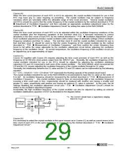
Incidentally, the high oscillation frequency of the crystal oscillator can also be adjusted by adding an external
oscillation stabilization capacitor CGOUT as illustrated in the diagram below.
*1) The CGOUT should have a capacitance ranging
from 0 to 15 pF.
OSCIN
CG
RD
Oscillator
Circuit
32kHz
OSCOUT
CGOUT
CD
Course (D)
It is necessary to select the crystal oscillator in the same manner as in Course (C) as well as correct errors in the
time count of each RTC in the same manner as in Course (B) by the method described in " P.30 ꢁ Oscillation
Adjustment Circuit ".
12345
Rev.2.01
- 29 -

 RICOH [ RICOH ELECTRONICS DEVICES DIVISION ]