Rx5C348A/B
ꢁ
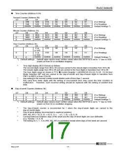
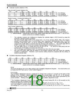
Calendar Counter (Address 4-6h)
Day-of-month Counter (Address 4h)
D7
-
D6
-
D5
D20
D4
D10
D3
D8
D2
D4
D1
D2
D0
D1
(For Writing)
0
0
0
0
D20
Indefinite
D10
Indefinite
D8
Indefinite
D4
Indefinite
D2
Indefinite
D1
Indefinite
(For Reading)
Default Settings *)
Month Counter + Century Bit (Address 5h)
D7
D6
D5
D4
D3
D2
D1
D0
-
-
MO10
MO8
MO4
MO2
MO1
(For Writing)
/19⋅20
0
0
0
0
MO10
Indefinite
MO8
Indefinite
MO4
Indefinite
MO2
Indefinite
MO1
Indefinite
(For Reading)
Default Settings *)
/19⋅20
Indefinite
Year Counter (Address 6h)
D7
Y80
D6
Y40
D5
Y20
D4
Y10
D3
Y8
D2
Y4
D1
Y2
D0
Y1
(For Writing)
Y80
Indefinite
Y40
Indefinite
Y20
Indefinite
Y10
Indefinite
Y8
Indefinite
Y4
Indefinite
Y2
Indefinite
Y1
Indefinite
(For Reading)
Default Settings *)
*) Default settings: Default value means read / written values when the XSTP bit is set to “1” due to VDD
power-on from 0v or oscillation stopping
*
The calendar counters are configured to display the calendar digits in BCD format by using the
automatic calendar function as follows:
The day-of-month digits (D20 to D1) range from 1 to 31 for January, March, May, July, August,
October, and December; from 1 to 30 for April, June, September, and November; from 1 to 29 for
February in leap years; from 1 to 28 for February in ordinary years. The day-of-month digits are
carried to the month digits in reversion from the last day of the month to 1. The month digits (MO10
to MO1) range from 1 to 12 and are carried to the year digits in reversion from 12 to 1.
The year digits (Y80 to Y1) range from 00 to 99 (00, 04, 08, …, 92, and 96 in leap years) and are
carried to the /19⋅20 digits in reversion from 99 to 00.
The /19⋅20 digits cycle between 0 and 1 in reversion from 99 to 00 in the year digits.
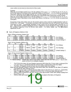
Any carry from lower digits with the writing of non-existent calendar data may cause the calendar
counters to malfunction. Therefore, such incorrect writing should be replaced with the writing of
existent calendar data.
*
ꢁ
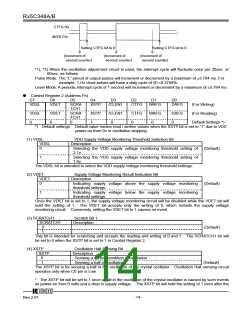
Oscillation Adjustment Register (Address 7h)
D7
(0)
(0)
0
D6
F6
F6
0
D5
F5
F5
0
D4
F4
F4
0
D3
F3
F3
0
D2
F2
F2
0
D1
F1
F1
0
D0
F0
F0
0
(For Writing)
(For Reading)
Default Settings *)
*) Default settings: Default value means read / written values when the XSTP bit is set to “1” due to VDD
power-on from 0v or oscillation stopping
(0) bit
The (0) bit should be set to 0 to allow writing to the Oscillation Adjustment Register. The (0) bit will be set
to 0 when the XSTP bit is set to 1 in the Control Register 2.
F6 to F0 bits
The Oscillation Adjustment Circuit is configured to change time counts of 1 second on the basis of the
settings of the Oscillation Adjustment Register when the second digits read 00, 20, or 40 seconds.
Normally, the Second Counter is incremented once per 32768 32.768-kHz clock pulses generated by the
crystal oscillator. Writing to the F6 to F0 bits activates the oscillation adjustment circuit.
* The Oscillation Adjustment Circuit will not operate with the same timing (00, 20, or 40 seconds) as the
timing of writing to the Oscillation Adjustment Register.
* The F6 bit setting of 0 causes an increment of time counts by ((F5, F4, F3, F2, F1, F0) - 1) x 2.
The F6 bit setting of 1 causes a decrement of time counts by ((/F5, /F4, /F3, /F2, /F1, /F0) + 1) x 2.
The settings of "*, 0, 0, 0, 0, 0, *" ("*" representing either "0" or "1") in the F6, F5, F4, F3, F2, F1, and F0 bits
12345
Rev.2.01
- 18 -

 RICOH [ RICOH ELECTRONICS DEVICES DIVISION ]