Rx5C348A/B
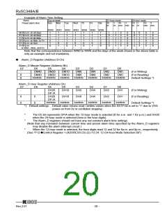
Example of Alarm Time Setting
Alarm
Day-of-week
Sun. Mon.
12-hour mode
24-hour mode
10 10
hr. min. min. hr. hr. min. min.
Preset alarm time
Tue.
Wed. Th.
Fri.
Sat.
10
hr.
1
10
1
1
1
WW0 WW1 WW2 WW3 WW4 WW5 WW6
00:00 a.m. on all days
01:30 a.m. on all days
11:59 a.m. on all days
00:00 p.m. on Mon. to Fri.
01:30 p.m. on Sun.
11:59 p.m.
1
1
1
0
1
0
1
1
1
1
0
1
1
1
1
1
0
0
1
1
1
1
0
1
1
1
1
1
0
0
1
1
1
1
0
1
1
1
1
0
0
0
1
2
1
1
2
1
1
0
3
5
0
3
5
0
0
9
0
0
9
0
0
1
1
1
2
0
1
1
2
3
3
0
3
5
0
3
5
0
0
9
0
0
9
0
1
3
2
3
on Mon. ,Wed., and Fri.
Note that the correspondence between WW0 to WW6 and the days of the week shown in the above table is
only an example and not mandatory.
ꢁ
Alarm_D Register (Address B-Ch)
Alarm_D Minute Register (Address Bh)
D7
D6
D5
D4
D3
D2
D1
D0
-
DM40
DM20
DM10
DM8
DM4
DM2
DM1
(For Writing)
0
0
DM40
Indefinite
DM20
Indefinite
DM10
Indefinite
DM8
Indefinite
DM4
Indefinite
DM2
Indefinite
DM1
Indefinite
(For Reading)
Default Settings *)
Alarm_D Hour Register (Address Ch)
D7
D6
D5
D4
D3
D2
D1
D0
-
-
DH20
DP⋅/A
DH20
DP⋅/A
Indefinite
DH10
DH8
DH4
DH2
DH1
(For Writing)
0
0
0
0
DH10
DH8
DH4
DH2
DH1
(For Reading)
Indefinite
Indefinite
Indefinite
Indefinite
Indefinite
Default Settings *)
*) Default settings: Default value means read / written values when the XSTP bit is set to “1” due to VDD
power-on from 0v or oscillation stopping
*
*
The D5 bit represents DP/A when the 12-hour mode is selected (0 for a.m. and 1 for p.m.) and DH20
when the 24-hour mode is selected (tens in the hour digits).
The Alarm_D registers should not have any non-existent alarm time settings.
(Note that any mismatch between current time and preset alarm time specified by the Alarm_D registers
may disable the alarm interrupt circuit.)
*
When the 12-hour mode is selected, the hour digits read 12 and 32 for 0a.m. and 0p.m., respectively.
(See "P12 ꢁControl Register 1 (ADDRESS Eh) (2) /12⋅24: 12-/24-hour Mode Selection Bit")
12345
Rev.2.01
- 20 -

 RICOH [ RICOH ELECTRONICS DEVICES DIVISION ]