Rx5C348A/B
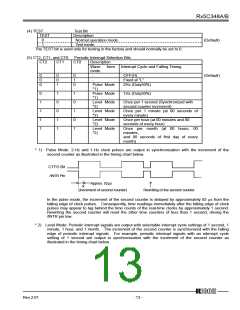
(4) TEST
TEST
Test Bit
Description
0
1
Normal operation mode.
Test mode.
(Default)
The TEST bit is used only for testing in the factory and should normally be set to 0.
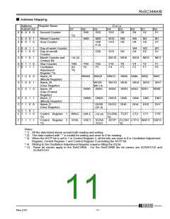
(5) CT2, CT1, and CT0 Periodic Interrupt Selection Bits
CT2
CT1
CT0
Description
Wave
form
Interrupt Cycle and Falling Timing
mode
0
0
0
0
0
1
0
1
0
-
-
OFF(H)
Fixed at “L”
2Hz (Duty50%)
(Default)
Pulse Mode
*1)
0
1
1
1
1
1
0
0
1
1
1
0
1
0
1
Pulse Mode
*1)
Level Mode
*2)
Level Mode
*2)
Level Mode
*2)
1Hz (Duty50%)
Once per 1 second (Synchronized with
second counter increment)
Once per 1 minute (at 00 seconds of
every minute)
Once per hour (at 00 minutes and 00
seconds of every hour)
Level Mode
*2)
Once per month (at 00 hours, 00
minutes,
and 00 seconds of first day of every
month)
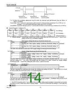
* 1) Pulse Mode: 2-Hz and 1-Hz clock pulses are output in synchronization with the increment of the
second counter as illustrated in the timing chart below.
CTFG Bit
/INTR Pin
Approx. 92µs
(Increment of second counter)
Rewriting of the second counter
In the pulse mode, the increment of the second counter is delayed by approximately 92 µs from the
falling edge of clock pulses. Consequently, time readings immediately after the falling edge of clock
pulses may appear to lag behind the time counts of the real-time clocks by approximately 1 second.
Rewriting the second counter will reset the other time counters of less than 1 second, driving the
/INTR pin low.
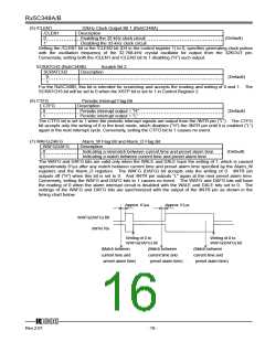
* 2) Level Mode: Periodic interrupt signals are output with selectable interrupt cycle settings of 1 second, 1
minute, 1 hour, and 1 month. The increment of the second counter is synchronized with the falling
edge of periodic interrupt signals. For example, periodic interrupt signals with an interrupt cycle
setting of 1 second are output in synchronization with the increment of the second counter as
illustrated in the timing chart below.
12345
Rev.2.01
- 13 -

 RICOH [ RICOH ELECTRONICS DEVICES DIVISION ]