RT8206A/B
Reference and Linear Regulator (REF, LDO and 14V
Charge Pump)
of Figure 3), will also increase the robustness of the charge
pump.
The 2V reference (REF) is accurate within 1% over
temperature, making REF useful as a precision system
reference. Bypass REF toGNDwith 0.22uF(MIN) capacitor.
REF can supply up to 50uA for external loads. Loading
REF degrades FBxand output accuracy according to the
REF load-regulation error.
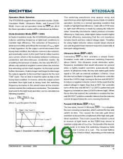
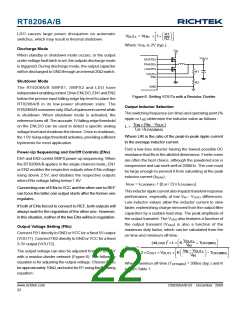
Current-Limit Setting (ILIMx)
The RT8206A/B has a cycle-by-cycle current limiting
control. The current-limit circuit employs a unique “valley”
current sensing algorithm. If the magnitude of the current-
sense signal at PHASEx is above the current-limit
threshold, the PWM is not allowed to initiate a new cycle
(Figure 4). The actual peak current is greater than the
current-limit threshold by an amount equal to the inductor
ripple current. Therefore, the exact current-limit
characteristic and maximum load capability are a function
of the sense resistance, inductor value, battery voltage,
and output voltage.
An internal regulator produces a fixed output voltage 5V.
The LDO regulator can supply up to 70mA for external
loads. Bypass LDO with a minimum 4.7μF ceramic
capacitor. When the output voltage of the VOUT1 is higher
than the switchover threshold, an internal 1.5ΩN-Channel
MOSFET switch connects VOUT1 to LDO through BYP
while simultaneously shutting down the internal linear
regulator.
I
L
I
L, peak
In typical application circuit figure, the external 14V charge
pump is driven by LGATE1. When LGATE1 is low, D1
charge C5 sourced from VOUT1. C5 voltage is equal to
VOUT1 minus a diode drop. When LGATE1 transitions to
high, the charge from C5 will transfer to C6 through D2
and charge it to VLGATE1 plus VC5. As LGATE1 transients
low on the next cycle, C6 will charge C7 to its voltage
minus a diode drop through D3. Finally, C7 charges C8
through D4 when LGATE1 transi switched to high. CP
output voltage is :
I
I
Load
LIM
t
0
Figure 4. Valley Current-Limit
The RT8206A/B uses the on-resistance of the synchronous
rectifier as the current-sense element. Use the worse-
case maximum value for RDS(ON) from the MOSFET
datasheet, and add a margin of 0.5%/°C for the rise in
RDS(ON) with temperature.
CP = VOUT1 +2 x VLGATE1 − 4 x VD
Where :
` VLGATE1 is the peak voltage of the LGATE1 driver
` VD is the forward diode dropped across the Schottkys
The current-limit threshold is adjusted with an external
resistor for the RT8206A/B at ILIMx. The current-limit
threshold adjustment range is from 50mV to 200mV. In
the adjustment mode, the current-limit threshold voltage
is precise to 1/10 the voltage seen at ILIMx. The threshold
defaults to 100mV when ILIMx is connected to VCC. The
logic threshold for switchover to the 100mV default value
is higher than VCC−1V.
SECFB (RT8206A) is used to monitor the charge pump
through resistive divider. In an event when SECFB drops
below 2V, the detection circuit forces the LGATE1 on for
300ns to allow CP to recharge and the SECFB rise above
2V. In the event of an overload on CP where SECFB can
not reach more than 2V, the monitor will be deactivated.
Carefully observe the PC board layout guidelines to ensure
that noise andDC errors do not corrupt the current-sense
signal at PHASEx and GND. Mount or place the IC close
to the low-side MOSFET.
The SECFB pin has a 17mV of hysteresis so the ripple
should be enough to bring the SECFB voltage above the
threshold by ~3x the hysteresis, or (3 x 17mV) = 51mV.
Reducing the CP decoupling capacitor and placing a small
ceramic capacitor C19 (10pF to 47pF) in parallel will the
upper leg of the SECFB resistor feedback network (R11
www.richtek.com
20
DS8206A/B-03 December 2009

 RICHTEK [ RICHTEK TECHNOLOGY CORPORATION ]