RT8206A/B
Operation Mode Selection
The switching waveforms may appear noisy and
asynchronous when light loading causesDiode-Emulation
operation, but this is a normal operating condition that
results in high light-load efficiency. Trade-offs in PFM noise
vs. light-load efficiency is made by varying the inductor
value. Generally, low inductor values produce a broader
efficiency vs. load curve, while higher values result in higher
full-load efficiency (assuming that the coil resistance
remains fixed) and less output voltage ripple. Penalties
for using higher inductor values include larger physical
size and degraded load-transient response (especially at
low input-voltage levels).
The RT8206A/B supports three operation modes:Diode-
Emulation Mode, Ultrasonic Mode, and Forced-CCM
Mode. Users can set operation mode by SKIP pin. All of
the three operation modes will be introduced as follows.
Diode-Emulation Mode (SKIP = GND)
InDiode-Emulation mode, the RT8206A/B automatically
reduces switching frequency at light-load conditions to
maintain high efficiency. This reduction of frequency is
achieved smoothly and without the increase of VOUTx ripple
or load regulation. As the output current decreases from
heavy-load condition, the inductor current is also reduced,
and eventually comes to the point that its valley touches
zero current, which is the boundary between continuous
conduction and discontinuous conduction modes. By
emulating the behavior of diodes, the low-side MOSFET
allows only partial of negative current when the inductor
free-wheeling current reach negative. As the load current
further decreases, it takes longer and longer to discharge
the output capacitor to the level that requires for the next
“ON” cycle. The on-time is kept the same as that in the
heavy-load condition. In reverse, when the output current
increases from light load to heavy load, the switching
frequency increases to the preset value as the inductor
current reaches the continuous conduction. The transition
load point to the light-load operation can be calculated as
following equation.
Ultrasonic Mode (SKIP = REF)
Connecting SKIP to REF activates a unique Diode-
Emulation mode with a minimum switching frequency
above 25kHz. This ultrasonic mode eliminates audio-
frequency modulation that would otherwise be present
when a lightly loaded controller automatically skips
pulses. In ultrasonic mode, the low-side switch gate-driver
signal is OR with an internal oscillator (>25kHz). Once
the internal oscillator is triggered, the ultrasonic controller
forces the LGATEx high, turning on the low-side MOSFET
to induce a negative inductor current. At the point that the
output voltage is higher than that of REF, the controller
turns off the low-side MOSFET (LGATEx pulled low) and
triggers a constant on-time (UGATExdriven high). When
the on-time has expired, the controller re-enables the low-
side MOSFET until the controller detects that the inductor
current dropped below the zero-crossing threshold.
(V − V
)
IN
OUT
I
≈
×T
ON
LOAD
2L
where TON is the given On-time.
Forced-CCM Mode (SKIP = VCC
)
The low-noise, forced-CCM mode (SKIP = VCC) disables
the zero-crossing comparator, which controls the low-side
switch on-time. This causes the low-side gate-driver
waveform to become the complement of the high-side gate-
driver waveform. This in turn causes the inductor current
to reverse at light loads as the PWM loop strives to
maintain a duty ratio of VOUT/VIN. The benefit of the forced-
CCM mode is to keep the switching frequency fairly
constant, but it comes at a cost : The no-load battery
current can be 10mAto 40mA, depending on the external
MOSFETs.
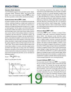
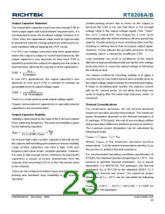
I
L
Slope = (V -V
) / L
OUT
IN
i
L, peak
i
= i
/ 2
L, peak
Load
t
0
t
ON
Figure 3. Boundary Condition of CCM/DEM
DS8206A/B-03 December 2009
www.richtek.com
19

 RICHTEK [ RICHTEK TECHNOLOGY CORPORATION ]