RT8206A/B
Application Information
input voltage as measured by the VIN, and proportional to
the output voltage. The on-time is given by :
The RT8206A/B is a dual, high efficiency, Mach
ResponseTM DRVTM dual ramp valley mode synchronous
buck controller. The controller is designed for low-voltage
power supplies for notebook computers. Richtek Mach
ResponseTM technology is specifically designed for
providing 100ns “instant-on” response to load steps while
maintaining a relatively constant operating frequency and
inductor operating point over a wide range of input voltages.
TheDRVTM mode PWM modulator is specifically designed
to have better noise immunity for such a dual output
application. The RT8206A/B achieves high efficiency at a
reduced cost by eliminating the current-sense resistor
found in traditional current-mode PWMs. Efficiency is
further enhanced by its ability to drive very large
synchronous rectifier MOSFETs. The RT8206A/B includes
5V (LDO) linear regulator which can step down the battery
voltage to supply both internal circuitry and gate drivers.
When VOUT1 voltage is above 4.66V, an automatic circuit
turns off the linear regulator and powers the device from
On-Time= K (VOUT / VIN)
There “K” is set by the TON pin-strap connector (Table
1). One-shot timing error increases for the shorter on-
time setting due to fixed propagation delays that is
approximately 15% at high frequency and the 10% at
low frequency. The on-time guaranteed in the Electrical
Characteristics tables is influenced by switching delays
in the external high-side power MOSFET. Two external
factors that influence switching-frequency accuracy are
resistive drops in the two conduction loops (including
inductor and PC board resistance) and the dead-time effect.
These effects are the largest contributors to the change
of frequency with changing load current. The dead-time
effect increases the effective on-time, reducing the
switching frequency as one or both dead times. It occurs
only in PWM mode (SKIP = high) when the inductor
current reverses at light or negative load currents. With
reversed inductor current, the inductor's EMF causes
PHASEX to go high earlier than normal, extending the on-
time by a period equal to the low-to-high dead time. For
loads above the critical conduction point, the actual
switching frequency is :
VOUT1 through BYP pin connected to VOUT1
.
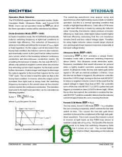
PWM Operation
The Mach ResponseTM DRVTM mode controller relies on
the output filter capacitor's effective series resistance
(ESR) to act as a current-sense resistor, so the output
ripple voltage provides the PWM ramp signal. Refer to the
function block diagram, the UGATE driver will be turned
on at the beginning of each cycle. After the internal one-
shot timer expires, the UGATE driver will be turned off.
The pulse width of this one shot is determined by the
converter's input voltage and the output voltage to keep
the frequency fairly constant over the input voltage range.
Another one-shot sets a minimum off-time (300ns typ.).
The on-time one-shot is triggered if the error comparator
is high, the low-side switch current is below the current-
limit threshold, and the minimum off-time one-shot has
timed out.
FS = (VOUT +VDROP1) / TON x (VIN + VDROP1 − VDROP2
)
The VDROP1 is the sum of the parasitic voltage drops in the
inductor discharge path, including synchronous rectifier,
inductor, and PC board resistances; VDROP2 is the sum of
the resistances in the charging path; and TON is the on-
time calculated by the RT8206A/B.
Table 1. TON Setting and PWM Frequency Table
TON
= VCC
TON
= REF
TON
= GND
TON
V
OUT1
5μs
3.33μs
2.5μs
K-Factor
V
OUT1
200kHz
300kHz
400kHz
Frequency
PWM Frequency and On-Time Control
V
OUT2
4μs
2.67μs
375kHz
±12.5%
2μs
The Mach ResponseTM control architecture runs with
pseudo-constant frequency by feed-forwarding the input
and output voltage into the on-time one-shot timer. The
high-side switch on-time is inversely proportional to the
K-Factor
V
OUT2
250kHz
±10%
500kHz
±15%
Frequency
Approximate
K-Factor Error
www.richtek.com
18
DS8206A/B-03 December 2009

 RICHTEK [ RICHTEK TECHNOLOGY CORPORATION ]