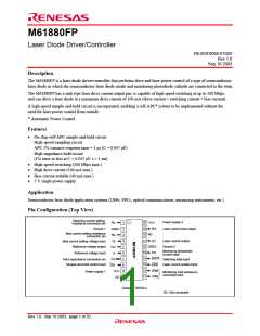
M61880FP
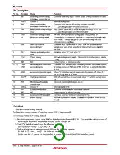
Pin Description
Pin No. Symbol
Name
Function
1
Rs
Switching current setting
resistance connection pin
Connects switching object current (ISW) setting resistance to GND.
2
3
GND1
RB
Ground 1
Internal analog GND
Bias current setting
resistance connection pin
Connects bias current (IB) setting resistance to GND.
Leave this pin open when IB is not used.
4
VB
Bias current setting voltage Bias current value (IB) is set by applying a voltage to this pin.
input
Leave this pin open when IB is not used.
5
6
Vref
Vr
Reference voltage output
Reference voltage input
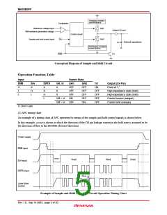
M61880 internal reference voltage (1.5 V typ.) output pin
Connected to non-reversed input pin of comparator in sample-and-
hold circuit. Connect this pin to Vref pin when using M61880
internal reference voltage.
7
CH
Hold capacitance
connection pin
Connects hold capacitance to GND. This pin is connected to
sample-and-hold circuit output and ISW current source input in
M61880.
8
9
S/H
Vcc1
NC
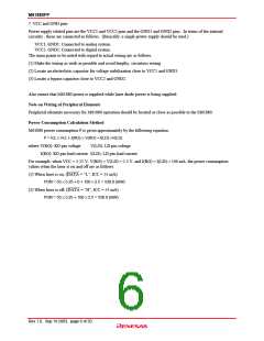
Sample-and-hold control
input
Sampling when “H”, hold when “L”
Power supply 1
Internal analog power supply. Connected to positive power supply
(+5 V).
10
NC
Not connected to internal circuitry.
11, 12
1RM
2RM
Monitoring load resistance
connection pins
Connects load resistance for converting monitor photodiode current
to voltage between 1RM and 2RM. (1RM pin is connected to GND
in IC.)
13
14
15
ENB
DATA
PD
Laser current enable input
Switching data input
When “H”, LD drive current source circuit is turned off. Also, CH
pin is forcibly fixed at “L” level.
ISW+IB current flows to laser diode when “+”, and IB current when
“H”.
Monitoring photodiode
current input
Connects monitor photodiode anode.
16
17
18
19
20
GND2
LD
Ground 2
Internal digital GND
Laser current output
NC
Connects semiconductor laser diode cathode.
Not connected to internal circuitry.
Connects laser current load resistance to Vcc.
NC
RO
Laser current load output
Power supply 2
Vcc2
Internal digital power supply. Connected to positive power supply
(+5 V).
Operation
1. Laser drive current setting method
The laser drive current consists of switching current ISW + bias current IB.
(1) Switching current ISW setting method
a. Decide the maximum current value ILD(MAX) to flow in the laser diode (LD). This is decided taking account of
the LD type, dispersion, temperature changes, secular changes, etc.
b. Find ISW (initial set value) from the following equation.
ISW (initial set value) = ILD(MAX)/1.9
c. Find switching current setting resistance RS from the following equation.
RS
[kΩ]
30 × Vref (1.5V) [V] / ISW (initial set value) [mA]
In this case the LD current can be controlled in a range of 10% to 90% of ISW (initial set value).
Rev.1.0, Sep.19.2003, page 3 of 20

 RENESAS [ RENESAS TECHNOLOGY CORP ]