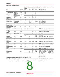
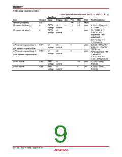
M61880FP
Application Example
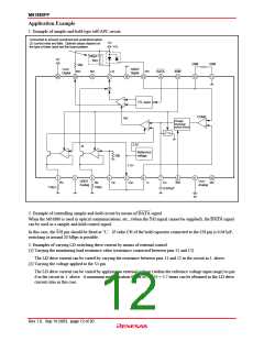
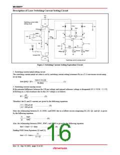
1. Example of sample-and-hold type self-APC circuit
Connected to prevent overshoot and undershoot when
LD current rises and falls. Optimal values depend on
the type of laser used and the board pattern.
5V
V
CC
100pF
5V
36Ω
2RM
12
1RM
11
10Ω
Vcc2
Digital
GND2
Digital
RO
19
NC
18
LD
17
PD
15
DATA
14
ENB
13
20
16
TTL input
COMP
I
SW
Charge/
discharge
control circuit
2.5V
I
B
Reference
voltage
50k
1.5V
1
2
3
4
5
6
7
8
9
10
GND1
Analog
Vcc1
Analog
RS
R
B
V
B
V
ref
V
r
C
H
S/H
NC
1.5kΩ
150Ω
0.047µF
5V
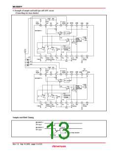
2. Example of controlling sample-and-hold circuit by means of DATA signal
When the M61880 is used in optical communications, etc., (when the S/H signal cannot be supplied), the DATA signal
can be used as a sample-and-hold control signal.
In this case, the S/H pin should be fixed at “L”. If value CH of the hold capacitor connected to the CH pin is 0.047µF,
switching at around 20 Mbps is possible.
3. Examples of varying LD switching drive current by means of external control
(1) Varying the monitoring load resistance value (resistance connected between pins 11 and 12)
The LD drive current can be varied by varying the resistance between pins 11 and 12 in the circuit in 1. above.
(2) Varying the voltage applied to the Vr pin
The LD drive current can be varied by applying an external voltage (within the reference voltage input range) to pin
6 in the circuit in 1. above. A maximum multiplication factor of 2/0.35 = 5.7 times can be obtained as the LD drive
current ratio in this case.
Rev.1.0, Sep.19.2003, page 12 of 20

 RENESAS [ RENESAS TECHNOLOGY CORP ]