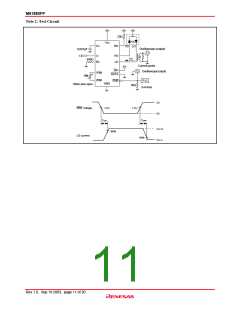
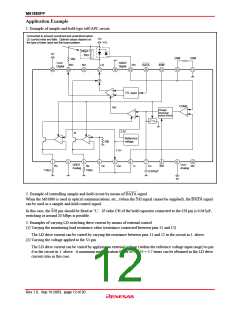
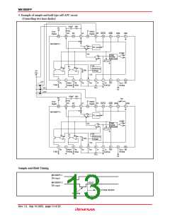
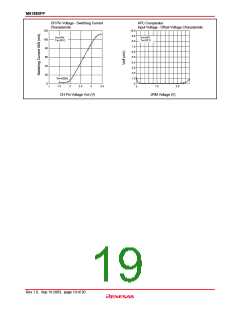
M61880FP
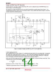
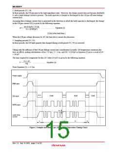
2. Hold periods (T2, T4)
In these periods, the CH pin goes to the high-impedance state. However, the charge current does not become absolutely
0, and a slight leakage current is present. The hold capacitor is charged or discharged by the CH pin off-state leakage
current (Ioz).
Assuming that a leakage current (Ioz) is generated in the direction in which the hold capacitor is discharged, the change
in the CH pin current (∆V) is given by the following equation.
Ioz (0.5µA) × T2 (4)
CH × (0.047µF)
∆V =
............................ Equation (2)
(T2(4) is the hold time.)
When the CH pin voltage decreases by ∆V, the laser drive current also decreases.
3. Sampling periods (T3, T5)
In these periods, the LD light quantity that changed during a hold period (T2, T4) is corrected.
Taking only the influence of the CH pin leakage current into consideration (actually, LD temperature variations also
have an effect), making substitutions of Ioz = 0.5µA, T = 1 ms, and CH = 0.047µF in Equation (2) gives a result of ∆V
= 10 mV.
The time required to compensate for this ∆V value (10 mV) is given by the following equation.
C
H
× ∆V
t =
............................ Equation (3)
Icg
From Equation (3), t = 0.7µs.
Power supply
ENB input
Sample
Sample
Sample
Hold
Hold
Hold
S/H input
DATA input
∆ILD
Laser drive
current
T1
T2
T3
T4
T5
Figure 2 Sample-and-Hold Type APC Circuit Operation Timing Chart
Rev.1.0, Sep.19.2003, page 15 of 20

 RENESAS [ RENESAS TECHNOLOGY CORP ]