M61880FP
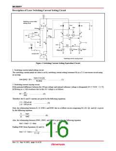
Description of Laser Switching Current Setting Circuit
V
CC
Switching current initial
setting circuit
1:1
I
SW1
D1
I1
D2
I2
V
B
I
SW2
2XISWO
2XISWO
AMP1
Q1 Q2
Vd
1.5V
I
SW2
V1
V2
I
SW
RS
V
CC
Id
2.5V
2kΩ
LD
2XISWO
250µA
250µA
Current SW
1:1
Switching current varying circuit
Figure 1 Switching Current Setting Equivalent Circuit
1. Switching current initial setting circuit
The switching current initial set value is set by switching current setting resistance Rs in a V-I conversion circuit using
an op-amp.
Vref (1.5V) [V]
I
SWO [mA] = 30 ×
............................ (1)
RS
[kΩ]
2. Switching current varying circuit
If the potential difference between the CH pin voltage and internal reference voltage is designated ∆V (= VCH – 2.5 V),
Id flowing in a 2 kΩ resistance due to this ∆V voltage is as follows.
∆V
Id =
............................ (2)
2kΩ
Therefore, the I1 and I2 currents are given by the following equations.
I1 = 250 µA-Id
I2 = 250 µA-Id
............................ (3)
Next, the relationship between I1, I2, ISW1, and ISW2 due to a Gilbert circuit comprising D1, D2, Q1, and Q2, is given
by the following equation.
I1
I2
Isw1
Isw2
=
............................ (4)
Also, the relationship between ISW1, ISW2, and ISW0 is given by the following equation.
Isw1 + Isw2 = 2 • Iswo ............................ (5)
Finding ISW2 from Equations (4) and (5),
I1
I
SW2 = 2 • ISWO ×
............................ (6)
I1 + I2
Rev.1.0, Sep.19.2003, page 16 of 20

 RENESAS [ RENESAS TECHNOLOGY CORP ]