M37161M8/MA/MF-XXXSP/FP,M37161EFSP/FP
Address 00F916
2
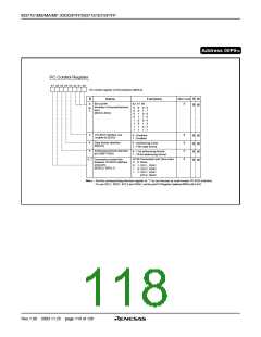
I C Control Register
b7 b6 b5 b4 b3 b2 b1 b0
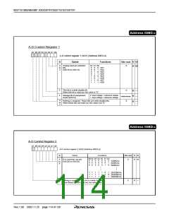
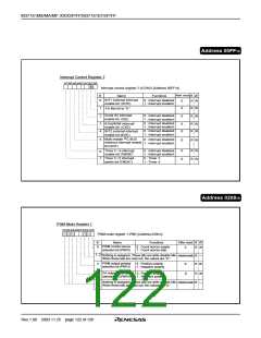
I2C control register (S1D) [Address 00F916
]
After reset
0
B
Name
Functions
R W
R W
Bit counter
(Number of transmit/recieve
b2 b1 b0
0
to
2
0
0
0
0
1
1
1
1
0
0
1
1
0
0
1
1
0 : 8
bits)
1 : 7
0 : 6
1 : 5
0 : 4
1 : 3
0 : 2
1 : 1
(BC0 to BC2)
3
4
5
I2C-BUS interface use
enable bit (ESO)
0
0
0
0
0 : Disabled
1 : Enabled
R W
R W
R W
R W
Data format selection
bit(ALS)
0 : Addressing mode
1 : Free data format
Addressing format selection
bit (10BIT SAD)
0 : 7-bit addressing format
1 : 10-bit addressing format
b7 b6 Connection port (See note)
6, 7 Connection control bits
between I2C-BUS interface
and ports
0
0
1
1
0: None
1: SCL1, SDA1
0: SCL2, SDA2
1: SCL1, SDA1
SCL2, SDA2
(BSEL0, BSEL1)
Note: • Set the corresponding direction register to "1" to use the port as multi-master I2C-BUS interface.
• To use SCL1, SDA1, SCL2 and SDA2, set the port P3 Register (address 00C616) bit 2 to 0.
Rev.1.00 2003.11.25 page 118 of 128

 RENESAS [ RENESAS TECHNOLOGY CORP ]