M37161M8/MA/MF-XXXSP/FP,M37161EFSP/FP
Address 00F716
2
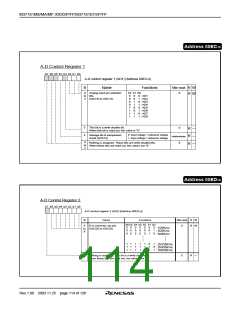
I C Address Register
b7 b6 b5 b4 b3 b2 b1 b0
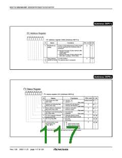
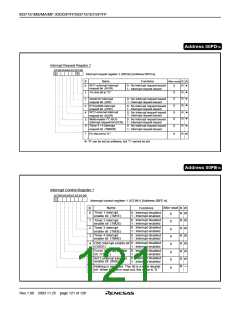
I2C address register (S0D) [Address 00F716
]
After reset
0
B
0
Name
Functions
R W
R
—
<Only in 10-bit addressing (in slave) mode>
The last significant bit of address data is
compared.
Read/write bit
(RBW)
0: Wait the first byte of slave address after
START condition
(read state)
1: Wait the first byte of slave address after
(write state)
RESTART condition
<In both modes>
(SAD0 to SAD6) The address data is compared.
R
W
Slave address
0
1
to
7
Address 00F816
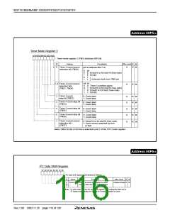
2
I
r
b7
b3 b2 b1 b0
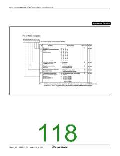
I2C status register (S1) [Address 00F816]
After reset
B
Name
Functions
W
R
0
1
2
Last receive bit (LRB)
(See note)
0 : Last bit = “0 ”
1 : Last bit = “1 ”
Indeterminate
R —
R —
R —
(See note)
General call detecting flag
(AD0) (See note)
0 : No general call detected
1 : General call detected
0
0
(See note)
Slave address comparison
flag (AAS) (See note)
0 : Address mismatch
1 : Address match
(See note)
(See note)
3
4
5
Arbitration lost detecting flag 0 : Not detected
(AL) (See note)
0
1
0
0
R —
R W
R W
R W
1 : Detected
I2C-BUS interface interrupt
request bit (PIN)
0 : Interrupt request issued
1 : No interrupt request issued
Bus busy flag (BB)
0 : Bus free
1 : Bus busy
6, 7 Communication mode
specification bits
b7 b6
0
0
1
1
0 : Slave recieve mode
1 : Slave transmit mode
0 : Master recieve mode
1 : Master transmit mode
(TRX, MST)
Note : These bits and flags can be read out, but cannnot be written.
Rev.1.00 2003.11.25 page 117 of 128

 RENESAS [ RENESAS TECHNOLOGY CORP ]