4283 Group
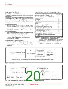
Table 7 Functions and states retained at RAM back-up
RAM BACK-UP MODE
The 4283 Group has the RAM back-up mode.
When the POF instruction is executed, system enters the RAM
back-up state.
As oscillation stops retaining RAM, the functions and states of
reset circuit at RAM back-up mode, power dissipation can be
reduced without losing the contents of RAM. Table 7 shows the
function and states retained at RAM back-up. Figure 24 shows
the state transition.
RAM back-up
Function
Program counter (PC), registers A, B,
carry flag (CY), stack pointer (SP) (Note 2)
Contents of RAM
✕
O
Port CARR
✕
O
Ports D0–D7
Ports E0, E1
O
Port G
O
(1) Warm start condition
Timer control registers V1, V2
Pull-down control registers PU0, PU1
Logic operation selection register LO
Timer 1 function, Timer 2 function
Timer underflow flags (T1F, T2F)
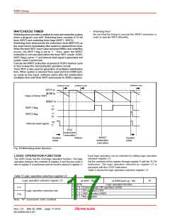
Watchdog timer (WDT)
✕
O
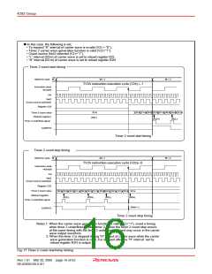
When the external wakeup signal is input after the system
enters the RAM back-up state by executing the POF
instruction, the CPU starts executing the software from address
0 in page 0. In this case, the P flag is “1.”
✕
✕
✕
✕
✕
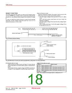
(2) Cold start condition
The CPU starts executing the software from address 0 in page
0 when any of the following conditions is satisfied .
• reset by power-on reset circuit is performed
• reset by watchdog timer is performed
• reset by voltage drop detection circuit is performed
In this case, the P flag is “0.”
Watchdog timer flags (WDF1, WDF2)
Most significant ROM code reference enable
flag (URS)
✕
Notes 1: “O” represents that the function can be retained, and
“✕” represents that the function is initialized.
Registers and flags other than the above are undefined
at RAM back-up, and set an initial value after returning.
2:The stack pointer (SP) points the level of the stack
register and is initialized to “112” at RAM back-up.
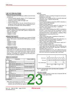
(3) Identification of the start condition
Warm start (return from the RAM back-up state) or cold start
(return from the normal reset state) can be identified by
examining the state of the power down flag (P) with the SNZP
instruction.
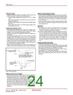
POF instruction
is executed
A
B
f(XIN) stop
(Stabilizing time a )
Reset
f(XIN) oscillation
(RAM back-up
mode)
Return input
(Stabilizing time a )
: Microcomputer starts its operation after f(XIN) is counted to16384 times.
Stabilizing time a
Fig. 24 State transition
Power down flag P
Software start
POF instruction
Reset input
S
Q
Yes
P = “1”
?
R
No
Warm start
Cold start
✕ Set source
✕ Clear source
POF instruction is executed
Reset input
Fig. 26 Start condition identified example using the SNZP
instruction
Fig. 25 Set source and clear source of the P flag
Rev.1.01 Mar 20, 2006 page 20 of 62
REJ03B0109-0101

 RENESAS [ RENESAS TECHNOLOGY CORP ]