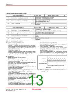
4283 Group
•
Watchdog timer
WATCHDOG TIMER
Be sure that the timing to execute the WRST instruction in
order to operate WDT efficiently.
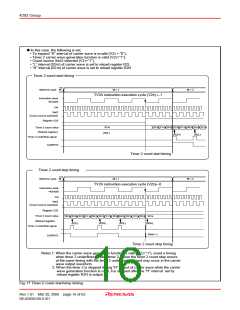
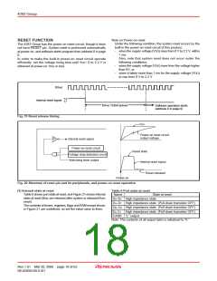
Watchdog timer provides a method to reset and restart the system
when a program runs wild. Watchdog timer consists of 14-bit
timer (WDT) and watchdog timer flags (WDF1, WDF2).
Watchdog timer downcounts the instruction clock (INSTCK) as
the count source immediately after system is released from reset.
When the timer WDT count value becomes 000016 and underflow
occurs, the WDF1 flag is set to “1.” Then, when the WRST
instruction is not executed before the timer WDT counts 16383,
WDF2 flag is set to “1” and internal reset signal is generated and
system reset is performed.
Execute the WRST instruction at period of 16383 machine cycle
or less to keep the microcomputer operation normal.
Timer WDT is also used for generation of oscillation stabilization
time. When system is returned from reset and from RAM back-
up mode by key-input, software starts after the stabilization
oscillation time until timer WDT downcounts to 3E0016 elapses.
Software start
Software start
Software start
3FFF16
3E0016
Value of timer WDT
0000 16
“1”
“0”
WDF1 flag
WDF2 flag
“1”
“0”
“H”
“L”
Internal reset signal
POF
instruction
execution
WRST
Return
System
reset
System
reset
instruction
execution
Fig. 18 Watchdog timer function
Each logic operation can be selected by setting logic operation
selection register LO.
Set the contents of this register through register A with the TLOA
instruction. The logic operation selected by register LO is
executed with the LGOP instruction.
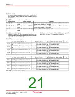
LOGIC OPERATION FUNCTION
The 4283 Group has the 4-bit logic operation function. The logic
operation between the contents of register A and the low-order 4
bits of register E is performed and its result is stored in register A.
Table 5 shows the logic operation selection register LO.
Table 5 Logic operation selection register LO
Logic operation selection register LO
at reset : 002
LO1 LO0
W
at RAM back-up : 002
Logic operation function
LO1
LO0
0
0
1
1
0
1
0
1
Exclusive logic OR operation (XOR)
OR operation (OR)
AND operation (AND)
Not available
Logic operation selection bits
Note: “W” represents write enabled.
Rev.1.01 Mar 20, 2006 page 17 of 62
REJ03B0109-0101

 RENESAS [ RENESAS TECHNOLOGY CORP ]