4283 Group
• Program counter (PC) .............................................................. 0
Address 0 in page 0 is set to program counter.
0
0
0
0
0
0
0
0
0
0
0
• Power down flag (P) ................................................................. 0
• Timer 1 underflow flag (T1F) ................................................... 0
• Timer 2 underflow flag (T2F) ................................................... 0
• Timer control register V1.......................................................... 0
• Timer control register V2.......................................................... 0
• Port CARR output flag (CAR) .................................................. 0
• Pull-down control register PU0 ................................................ 0
• Pull-down control register PU1 ................................................ 0
• Logic operation selection register LO ...................................... 0
0
0
0
0
0
0
0
0
0
0
0
• Most significant ROM code reference enable flag (URS)
0
• Carry flag (CY) ......................................................................... 0
• Register A................................................................................. 1
• Register B................................................................................. 1
1
1
1
1
1
1
• Register X................................................................................. ✕ ✕
• Register Y................................................................................. ✕ ✕ ✕ ✕
• Stack pointer (SP) .................................................................... 1
1
“✕” represents undefined.
Fig. 21 Internal state at reset
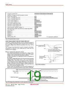
VOLTAGE DROP DETECTION CIRCUIT
The built-in voltage drop detection circuit is designed to detect a
drop in voltage at operating and to reset the microcomputer if
the supply voltage drops below the specified value (Typ. 1.50 V)
or less.
V
DD
Recommended operatng
condition min.value
The voltage drop detection circuit is stopped and power
dissipation is reduced in the RAM back-up mode with the
initialized CPU stopped.
Oscillation is stopped
incorrectly.
V
DET
Even if the voltage re-goes up to
the recommended operating voltage,
MCU may not operate correctly.
Note on voltage drop detection circuit
The voltage drop detection circuit detection voltage of this
product is set up lower than the minimum value of the supply
voltage of the recommended operating conditions.
A battery exchange of an application product is explained as
an example.
The supply voltage falls below to the recommended operating
voltage while CPU keeps active. Then, an unexpected
oscillation-stop, which does not happen by POF instruction
occurs before the supply voltage falls below to the detection
voltage. In this time, even if the supply voltage re-goes up to
the recommended operating voltage, since reset does not
occur, MCU may not operate correctly.
→ Normal operation
V
DD
Recommended
operatng condition
min.value
V
DET
Reset
Fig. 23 VDD and VDET
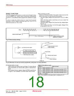
Please confirm the oscillator you use and the frequency of
system clock, and test the operation of your system sufficiently.
VDD
(Note)
Reset voltage
TYP 1.5V
Microcomputer starts operation
after f(XIN) is counted to 16384 times.
Internal reset signal
Note: The voltage drop detection circuit does not have
the hysteresis characteristics in the detected voltage.
Fig. 22 Voltage drop detection circuit operation waveform
Rev.1.01 Mar 20, 2006 page 19 of 62
REJ03B0109-0101

 RENESAS [ RENESAS TECHNOLOGY CORP ]