4283 Group
(3) Timer 1
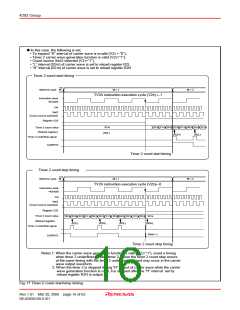
to “1”. Then, the “H” interval data of carrier wave is reloaded
from the reload register R2H, and count continues.
When timer underflows again after auto-reload, the T2F flag
is set to “1”. And then, the “L” interval data of carrier wave is
reloaded from the reload register R2L, and count continues.
After that, each timer underflows, data is reloaded from reload
register R2H and R2L alternately.
Timer 1 is an 8-bit binary down counter with the timer 1 reload
register (R1).
When timer is stopped, data can be set simultaneously in timer
1 and the reload register (R1) with the T1AB instruction.
When timer is operating, data can be set to only reload register
R1 with the T1AB instruction.
When setting the next count data to reload register R1 at
operating, set data before timer 1 underflows.
Timer 1 starts counting after the following process;
➁ set data in timer 1,
When a value set in reload register R2H is n, “H” interval of
carrier wave is as follows;
➁ When to expand “H” interval is invalid (V23 = “0”),
Count source ➁ (n+1), n = 0 to 255
➁ select the count source with the bit 1 of register V1, and
➁ set the bit 0 of register V1 to “1.”
➁ When to expand “H” interval is valid (V23 = “1”),
Count source ➁ (n+1.5), n = 1 to 255
Once count is started, when timer 1 underflows (the next count
pulse is input after the contents of timer 1 becomes “0”), the
timer 1 underflow flag (T1F) is set to “1,” new data is loaded
from reload register R1, and count continues (auto-reload
function).
When a value set in reload register R2L is m, “L” interval of
carrier wave is as follows;
Count source ➁ (m+1), m = 0 to 255
Data can be read from timer 2 to registers A and B. When
reading the data, stop the counter and then execute the TAB2
instruction.
When a value set in reload register R1 is n, timer 1 divides the
count source signal by n + 1 (n = 0 to 255).
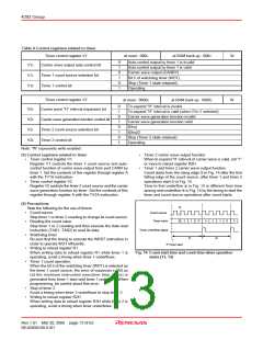
When the bit 2 of register V1 is set to “1,” the carrier wave
output enable/disable interval of port CARR is alternately
generated each timer 1 underflows (Figure 15).
Data can be read from timer 1 to registers A and B. When
reading the data, stop the counter and then execute the TAB1
instruction.
(5) Timer underflow flags (T1F, T2F)
Timer 1 underflow flag or timer 2 underflow flag is set to “1”
when the timer 1 or timer 2 underflows. The state of flags T1F
and T2F can be examined with the skip instruction (SNZT1,
SNZT2).
Flags T1F and T2F are cleared to “0” when the next instruction
is skipped with a skip instruction.
(4) Timer 2
Timer 2 is an 8-bit binary down counter with the timer 2 reload
registers (R2H and R2L).
Data can be set simultaneously in timer 2 and the reload
register (R2L) with the T2AB instruction.
The contents of reload register (R2L) set with the T2AB
instruction can be set again to timer 2 with the T2R2L
instruction. Data can be set to reload register (R2H) with the
T2HAB instruction.
Timer 2 starts counting after the following process;
➁ set data in timer 2,
➁ select the count source with the bit 1 of register V2, and
➁ select the valid/invalid of the carrier wave generation
function by bit 2 of register V1 (when this function is valid,
select the valid/invalid of the carrier wave “H” interval
expansion by bit 3), and
➁ set the bit 0 of register V1 to “1.”
When the carrier wave generation function is invalid (V22=“0”),
the following operation is performed;
Once count is started, when timer 2 underflows (the next count
pulse is input after the contents of timer 2 becomes “0”), the
timer 2 underflow flag (T2F) is set to “1,” new data is loaded
from reload register R2L, and count continues (auto-reload
function).
When a value set in reload register R2L is n, timer 2 divides
the count source signal by n + 1 (n = 0 to 255).
When the carrier wave generation function is valid (V22=“1”),
the carrier wave which has the “L” interval set to the reload
register R2L and “H” interval set to the reload register R2H
can be output (Figure 16).
After the count of the “L” interval of carrier wave is started,
timer 2 underflows and the timer 2 underflow flag (T2F) is set
Rev.1.01 Mar 20, 2006 page 14 of 62
REJ03B0109-0101

 RENESAS [ RENESAS TECHNOLOGY CORP ]