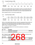
Bit 2—Multiprocessor Mode (MP): This bit selects the multiprocessor format in asynchronous
communication. When multiprocessor format is selected, the parity settings of the parity enable bit
(PE) and parity mode bit (O/E) are ignored. The MP bit is ignored in synchronous communication.
The MP bit is valid only when the MPE bit in the serial/timer control register (STCR) is set to 1.
When the MPE bit is cleared to 0, the multiprocessor communication function is disabled
regardless of the setting of the MP bit.
Bit 2: MP
Description
0
1
Multiprocessor communication function is disabled.
Multiprocessor communication function is enabled.
(Initial value)
Bits 1 and 0—Clock Select 1 and 0 (CKS1 and CKS0): These bits select the clock source of the
on-chip baud rate generator.
Bit 1: CKS1
Bit 0: CKS0
Description
ø clock
0
0
1
0
1
(Initial value)
øP/4 clock
øP/16 clock
øP/64 clock
1
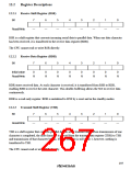
12.2.6
Serial Control Register (SCR)
Bit
7
TIE
0
6
5
TE
0
4
RE
0
3
2
1
0
RIE
0
MPIE
0
TEIE
0
CKE1
0
CKE0
0
Initial value
Read/Write
R/W
R/W
R/W
R/W
R/W
R/W
R/W
R/W
SCR is an 8-bit readable/writable register that enables or disables various SCI functions.
It is initialized to H'00 by a reset and in the standby modes.
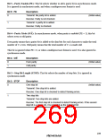
Bit 7—Transmit Interrupt Enable (TIE): This bit enables or disables the TDR-empty interrupt
(TXI) requested when the transmit data register empty (TDRE) bit in the serial status register
(SSR) is set to 1.
Bit 7: TIE
Description
0
1
The TDR-empty interrupt request (TXI) is disabled.
The TDR-empty interrupt request (TXI) is enabled.
(Initial value)
240

 RENESAS [ RENESAS TECHNOLOGY CORP ]