12.1.4
Register Configuration
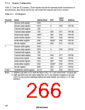
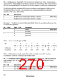
Table 12.2 lists the SCI registers. These registers specify the operating mode (synchronous or
asynchronous), data format and bit rate, and control the transmit and receive sections.
Table 12.2 SCI Registers
Initial
Channel
Name
Abbreviation
RSR
R/W
—
Value
Address
—
0
Receive shift register
Receive data register
Transmit shift register
Transmit data register
Serial mode register
Serial control register
Serial status register
Bit rate register
—
RDR
R
H'00
—
H'FFDD
—
TSR
—
TDR
SMR*2
R/W
R/W
R/W
R/(W)*1
R/W
—
H'FF
H'00
H'00
H'84
H'FF
—
H'FFDB
H'FFD8
H'FFDA
H'FFDC
H'FFD9
—
SCR
SSR
BRR*2
1
Receive shift register
Receive data register
Transmit shift register
Transmit data register
Serial mode register
Serial control register
Serial status register
Bit rate register
RSR
RDR
R
H'00
—
H'FF8D
—
TSR
—
TDR
R/W
R/W
R/W
R/(W)*1
R/W
R/W
H'FF
H'00
H'00
H'84
H'FF
H'00
H'FF8B
H'FF88
H'FF8A
H'FF8C
H'FF89
H'FFC3
SMR
SCR
SSR
BRR
0 and 1
Serial/timer control register
STCR
Notes: *1 Software can write a 0 to clear the flags in bits 7 to 3, but cannot write 1 in these bits.
*2 SMR and BRR have the same addresses as I2C bus interface registers ICCR and
ICSR. For the access switching method and other details, see section 13, I2C Bus
Interface.
236

 RENESAS [ RENESAS TECHNOLOGY CORP ]