12.2.4
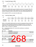
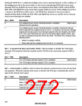
Transmit Data Register (TDR)
Bit
7
6
5
4
3
2
1
0
Initial value
Read/Write
1
1
1
1
1
1
1
1
R/W
R/W
R/W
R/W
R/W
R/W
R/W
R/W
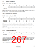
TDR is an 8-bit readable/writable register that holds the next data to be transmitted. When TSR
becomes empty, the data written in TDR is transferred to TSR. Continuous data transmission is
possible by writing the next data in TDR while the current data is being transmitted from TSR.
TDR is initialized to H'FF by a reset and in the standby modes.
12.2.5
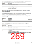
Serial Mode Register (SMR)
Bit
7
6
5
PE
0
4
3
STOP
0
2
MP
0
1
CKS1
0
0
CKS0
0
C/A
0
CHR
0
O/E
0
Initial value
Read/Write
R/W
R/W
R/W
R/W
R/W
R/W
R/W
R/W
SMR is an 8-bit readable/writable register that controls the communication format and selects the
clock source of the on-chip baud rate generator. It is initialized to H'00 by a reset and in the
standby modes. For further information on the SMR settings and communication formats, see
tables 12.5 and 12.7 in section 12.3, Operation.
Bit 7—Communication Mode (C/A): This bit selects asynchronous or synchronous
communication mode.
Bit 7: C/A
Description
0
1
Asynchronous communication
Synchronous communication
(Initial value)
Bit 6—Character Length (CHR): This bit selects the character length in asynchronous mode.
It is ignored in synchronous mode.
Bit 6: CHR
Description
0
1
8 bits per character
(Initial value)
7 bits per character (Bits 0 to 6 of TDR and RDR are used for transmitting and
receiving, respectively.)
238

 RENESAS [ RENESAS TECHNOLOGY CORP ]