Section 17 I2C Bus Interface 2 (IIC2)
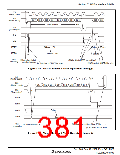
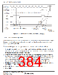
SCL
9
1
2
3
4
5
6
7
8
9
(Master output)
SDA
(Master output)
A
A/A
SDA
(Slave output)
Bit 7 Bit 6
Bit 5
Bit 4
Bit 3
Bit 2
Bit 1
Bit 0
RDRF
RCVD
ICDRS
ICDRR
Data n
Data n-1
Data n
Data n-1
User
processing
[7] Read ICDRR,
and clear RCVD
[5] Read ICDRR after setting RCVD
[6] Issue stop
condition
[8] Set slave
receive mode
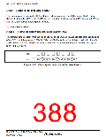
Figure 17.8 Master Receive Mode Operation Timing (2)
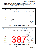
Slave Transmit Operation
17.4.4
In slave transmit mode, the slave device outputs the transmit data, while the master device outputs
the receive clock and returns an acknowledge signal. For slave transmit mode operation timing,
refer to figures 17.9 and 17.10.
The transmission procedure and operations in slave transmit mode are described below.
1. Set the ICE bit in ICCR1 to 1. Set the MLS and WAIT bits in ICMR and the CKS3 to CKS0
bits in ICCR1 to 1. (Initial setting) Set the MST and TRS bits in ICCR1 to select slave receive
mode, and wait until the slave address matches.
2. When the slave address matches in the first frame following detection of the start condition,
the slave device outputs the level specified by ACKBT in ICIER to SDA, at the rise of the 9th
clock pulse. At this time, if the 8th bit data (R/W) is 1, the TRS and ICSR bits in ICCR1 are
set to 1, and the mode changes to slave transmit mode automatically. The continuous
transmission is performed by writing transmit data to ICDRT every time TDRE is set.
3. If TDRE is set after writing last transmit data to ICDRT, wait until TEND in ICSR is set to 1,
with TDRE = 1. When TEND is set, clear TEND.
4. Clear TRS for the end processing, and read ICDRR (dummy read). SCL is free.
5. Clear TDRE.
Rev. 3.00 Sep. 10, 2007 Page 350 of 528
REJ09B0216-0300

 RENESAS [ RENESAS TECHNOLOGY CORP ]