Section 17 I2C Bus Interface 2 (IIC2)
SCL
(Master output)
1
2
3
4
5
6
7
8
9
1
2
SDA
(Master output)
Bit 7
Bit 6
Bit 5
Bit 4
Bit 3
Bit 2
Bit 1
Bit 0
Bit 7
Bit 6
Slave address
R/W
SDA
(Slave output)
A
TDRE
TEND
ICDRT
ICDRS
Address + R/W
Data 1
Data 1
Data 2
Address + R/W
User
processing
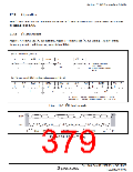
[2] Instruction of start
condition issuance
[4] Write data to ICDRT (second byte)
[5] Write data to ICDRT (third byte)
[3] Write data to ICDRT (first byte)
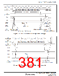
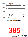
Figure 17.5 Master Transmit Mode Operation Timing (1)
SCL
(Master output)
9
1
2
3
4
5
6
7
8
9
SDA
(Master output)
Bit 7
Bit 6
Bit 5
Bit 4
Bit 3
Bit 2
Bit 1
Bit 0
SDA
(Slave output)
A
A/A
TDRE
TEND
ICDRT
ICDRS
Data n
Data n
User
processing
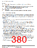
[6] Issue stop condition. Clear TEND.
[7] Set slave receive mode
[5] Write data to ICDRT
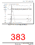
Figure 17.6 Master Transmit Mode Operation Timing (2)
Rev. 3.00 Sep. 10, 2007 Page 347 of 528
REJ09B0216-0300

 RENESAS [ RENESAS TECHNOLOGY CORP ]