Section 17 I2C Bus Interface 2 (IIC2)
17.4
Operation
The I2C bus interface can communicate either in I2C bus mode or clock synchronous serial mode
by setting FS in SAR.
17.4.1
I2C Bus Format
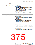
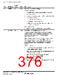
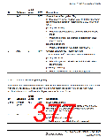
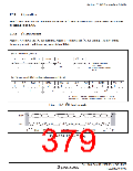
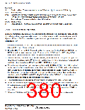
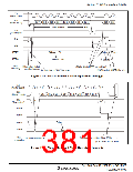
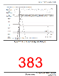
Figure 17.3 shows the I2C bus formats. Figure 17.4 shows the I2C bus timing. The first frame
following a start condition always consists of 8 bits.
(a) I2C bus format (FS = 0)
S
1
SLA
7
R/W
A
1
DATA
n
A
1
A/A
P
1
1
1
n: Transfer bit count
(n = 1 to 8)
1
m
m: Transfer frame count
(m ≥ 1)
(b) I2C bus format (Start condition retransmission, FS = 0)
S
1
SLA
7
R/W
A
1
DATA
n1
A/A
S
1
SLA
7
R/W
A
1
DATA
n2
A/A
P
1
1
1
1
1
1
m1
1
m2
n1 and n2: Transfer bit count (n1 and n2 = 1 to 8)
m1 and m2: Transfer frame count (m1 and m2 ≥ 1)
Figure 17.3 I2C Bus Formats
SDA
1-7
8
9
1-7
8
9
1-7
8
9
SCL
S
SLA
R/W
A
DATA
A
DATA
A
P
Figure 17.4 I2C Bus Timing
Rev. 3.00 Sep. 10, 2007 Page 345 of 528
REJ09B0216-0300

 RENESAS [ RENESAS TECHNOLOGY CORP ]