Section 12 Timer V
Initial
Bit
2
Bit Name Value
R/W
R/W
R/W
R/W
Description
CKS2
CKS1
CKS0
0
0
0
Clock Select 2 to 0
1
These bits select clock signals to input to TCNTV and the
counting condition in combination with ICKS0 in TCRV1.
0
Refer to table 12.2.
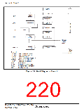
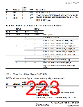
Table 12.2 Clock Signals to Input to TCNTV and Counting Conditions
TCRV0
Bit 1
CKS1
0
TCRV1
Bit 2
CKS2
0
Bit 0
CKS0
0
Bit 0
ICKS0
Description
0
Clock input prohibited
1
Internal clock: counts on φ/4, falling edge
Internal clock: counts on φ/8, falling edge
Internal clock: counts on φ/16, falling edge
Internal clock: counts on φ/32, falling edge
Internal clock: counts on φ/64, falling edge
Internal clock: counts on φ/128, falling edge
Clock input prohibited
1
1
0
1
0
1
0
1
1
0
1
0
1
0
1
External clock: counts on rising edge
External clock: counts on falling edge
External clock: counts on rising and falling
edge
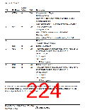
12.3.4
Timer Control/Status Register V (TCSRV)
TCSRV indicates the status flag and controls outputs by using a compare match.
Initial
Bit
Bit Name Value
R/W
Description
7
CMFB
0
R/W
Compare Match Flag B
Setting condition:
When the TCNTV value matches the TCORB value
Clearing condition:
After reading CMFB = 1, cleared by writing 0 to CMFB
Rev. 3.00 Sep. 10, 2007 Page 189 of 528
REJ09B0216-0300

 RENESAS [ RENESAS TECHNOLOGY CORP ]